Sir Mile, thanks for your reply. so if say i wanted to run the hv23 at between 90-0-90vdc and 100-0-100vdc, how many more irfp240/9240 outputs can i add so that i run safely at 4ohms?
regards.
regards.
Allow a total device power rating of 4times the maximum power that you set as your target from a ClassAB amplifier.
eg.
if you want 850W into 4ohms then use 4*850 = 3400W of output devices.
If you have some 150W devices, then 11pairs get you to 3300, close enough.
You might get away with 10pairs if you keep it cool enough.
ClassG/H may get away with as few as half this number because most of the time the devices only see 1/3rd to 1/2hf of the Vds voltage.
have in mind that this are 200V devices. so +/-100V is on the edge of killing the outputs.
i would not go over +/-90V.
i would not go over +/-90V.
thanks AndrewT and AudioSan for your replys. AudioSan, i agree they are 200v mosfets but i did a measurement on an amplifier's output using a psu of +/-67vdc. i thought i will get 134vdc between the drain and source but instead i got 67vdc. i did the same test on a bipolar amp and still got half the psu voltage between collector and emmitor. so i concluded that the only way to measure the max voltage between drain and source or collector and emmiter is to connect exactly that voltage. i beg to be corrected if am wrong.
AndrewT i think i will do some calculations also to come up with the neccesary upgrades for the amp.
AndrewT i think i will do some calculations also to come up with the neccesary upgrades for the amp.
when the output node is centrally located at the middle of the supply rail voltages the voltage across the +ve side device/s is +ve supply minus ground voltage. The voltage across the -ve side device/s is the -ve supply minus the ground voltage.
When the output moves away from that central location i.e. develops a voltage relative to ground, one side devices sees a higher voltage and the other side devices sees a lower voltage.
In the extreme, when the amplifier is producing maximum output the devices see the full rail to rail voltage alternately as the output swings either side of ground.
a +-100Vdc supply can impose 200Vds across the output device.
If the mains voltage goes up 5%, then the worst case voltage across the devices can be 210Vds.
Good evening,
Thanks AndrewT for your post. i have done my homework and i have concluded that i will try class H as an ultimate solution
Thanks AndrewT for your post. i have done my homework and i have concluded that i will try class H as an ultimate solution
Hi Sir Mile,
on a thread i started, AndrewT helped me estimate va rating for an old transformer that was just gathering dust. they are:
Primary:220vac-240vac 2020VA
secondary:+/-35vac 1970VA
+/-18vac 148VA.
with these figures, i would like to make another HV23 amplifier. what changes can i make if any and if this amplifier is not a good choice, which circuit would you recommend?
regards
Hi Sir Mile,
on a thread i started, AndrewT helped me estimate va rating for an old transformer that was just gathering dust. they are:
Primary:220vac-240vac 2020VA
secondary:+/-35vac 1970VA
+/-18vac 148VA.
with these figures, i would like to make another HV23 amplifier. what changes can i make if any and if this amplifier is not a good choice, which circuit would you recommend?
regards
No changes,
Regards
Hi Sir Mile,
i would like to increase the number of power outputs for stereo to 7 pairs. is that still okay?
i would like to increase the number of power outputs for stereo to 7 pairs. is that still okay?
the 35+35Vac secondary will give you ~ ±50Vdc
That allows a BJT output stage to give ~100W into 8ohms, or 200W into 4ohms.
With 1970VA available you could run ten 200W channels for domestic style (non PA) amplification. For PA duty you may have to reduce this to 5channels of 200W into 4ohms.
You could bridge these, or build balanced power amplifiers and get upto 5 channels of 400W into 8ohms.
Alternatively you could make some, or all, of your amp channels ClassA.
Using 6times to 10times as the VA required for each ClassA output watt, you could have 200W to 300W of total ClassA power amplification, i.e. two or three channels of 100W into 8ohms ClassA
The Krell KSA100 uses a 1kVA transformer for 100W into 8ohms in full ClassA and it transitions into ClassAB to do 200W into 4ohms or 400W into 2ohms. I power tested my Krell Klone at 411W into 2r0 test load.
Last edited:
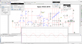
Input impedance is about 10 000 ohms
this data is to use a 10k volume control or am I wrong?
You could bridge these, or build balanced power amplifiers and get upto 5 channels of 400W into 8ohms.
Or, -with some extra output devices-, 800W/4ohms bridged is possible too.
Sajti
You know how to build good 2ohms capable amplifiers !Or, -with some extra output devices-, 800W/4ohms bridged is possible too.
Sajti
Are you going to give him lessons?
You know how to build good 2ohms capable amplifiers !
Are you going to give him lessons?
I did some... I guess, that 6-7 pairs would be OK, and some higher voltage for the input+VAS, to reduce the loss.
Sajti
Hello,
took me four 22000uF 100V capacitors and two 500VA toroidal ... really great amplifier ....
😱😱
Apexaudio, in your opinion which preamp is better to combine with this amplifier?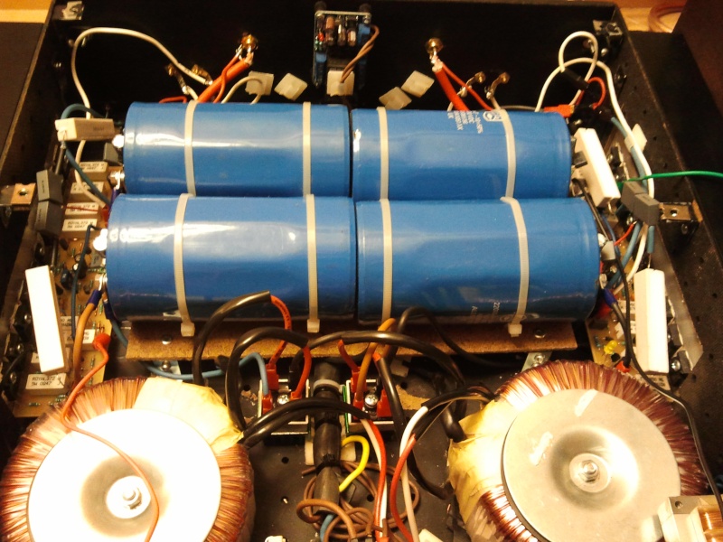
There is many preamps... use this circuit.
Attachments

- Home
- Amplifiers
- Solid State
- MOSFET Amplifier IRFP240/IRFP9240