This is very philosophical and mostly untrue. A structure of many transistors is necessary for the linearity of the characteristics of only 2 amplification stages. The quality of the structure depends on the literacy of the design engineer; the efforts to develop the structure must have some meaning.Simple is better (below).
Example in your circuit: Q6Q7 are needed to facilitate the operation of the Q4Q5 input differential stage with a high-voltage power supply - this reduces the signal-to-noise ratio, but their contribution to the linearity of the amplifier is very small, only 2 dB, against the background of 80 dB open loop - this is a drop in the ocean. In your case, the base of these Q6Q7 transistors in terms of alternating voltage is not fixed to the GND, which means their high capacitance for an alternating signal - and the immediate question is what is the point of this?
in your solution, the work of this cascade is more complex than the rest of the circuit combined. And where is your simplicity?
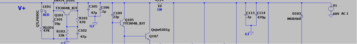
P.S. In your diagram in the attachment, C3 is included incorrectly.
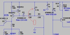
Q11 Q12 Q13 with 2-pole correction C6C7R18 This is nonsense topology for sound.
Last edited:
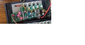
But if you can "kill 2 bird's with one stone' , why not !! C3 is perfect - that amp is REAL (below). tested and ready for prime time (below) !
C3 is 1/2 Vcc - decoupling for the 2Q CCS. 5ppm 100w + .2mV offset.
PS - wolverine (same IPS) is second only to a 100K$ "Halcro" audiofool amp , it has 17 devices for it's IPS. My 2 symmetric designs are 20+ devices ,
but only because they are symmetric . Still, <5PPM + -100db psrr.
OS
C3 is 1/2 Vcc - decoupling for the 2Q CCS. 5ppm 100w + .2mV offset.
PS - wolverine (same IPS) is second only to a 100K$ "Halcro" audiofool amp , it has 17 devices for it's IPS. My 2 symmetric designs are 20+ devices ,
but only because they are symmetric . Still, <5PPM + -100db psrr.
OS
Attachments
Last edited:

check or you drew it incorrectly in the diagram or do not write that it is perfect.C3 is perfect
Exectly, because there is no benefit from it, it’s just a detail on the board that doesn’t affect anything. )))that amp is REAL (below). tested and ready for prime time (below)
Attachments
Last edited:
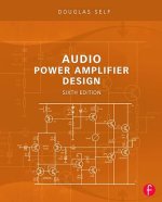
I’m glad that you are familiar with this book, now look at this damn shell and your diagram, if you can’t see it, look at the attachment.front cover .... 1/2Vcc reference for both LTP and VAS current sources , "C3" - right on damn front cover of the bloody book !
P.S. C3 should increase the alternating voltage resistance of the circuit of resistors R4R5, and not decrease it as in your picture - it’s just like elementary school.
Attachments

In your case, the base of these Q6Q7 transistors in terms of alternating voltage is not fixed to the GND, which means their high capacitance for an alternating signal - and the immediate question is what is the point of this?
in your solution, the work of this cascade is more complex than the rest of the circuit combined. And where is your simplicity?
He sacrificed Q6-Q7 to have constant Vce voltage on Q4-Q5. In this way, it eliminates input Ccb (Miller effect) and the Early effect in Q4-Q5. It's a clever design.
Ok , your right ... but I'm using the 2Q , not the diodes. c3 my way is (slightly) better >100hz , but I lose 3db at <100hz. Still real low @40-60hz.
not much change between either C3 position. Added bypass of R10 = no change (PSRR or THD) , omit it...
It might make a big difference with a diode CCS... Badger is a diode CCS , decoupling goes to rail.
PS - I though you meant even HAVING C3 was wrong - to omit it. Which ,with the 2Q , I could.
not much change between either C3 position. Added bypass of R10 = no change (PSRR or THD) , omit it...
It might make a big difference with a diode CCS... Badger is a diode CCS , decoupling goes to rail.
PS - I though you meant even HAVING C3 was wrong - to omit it. Which ,with the 2Q , I could.
Attachments
The input R1C5 filter frequency is much lower than the frequency at which the Miller effect occurs.He sacrificed Q6-Q7 to have constant Vce voltage on Q4-Q5. In this way, it eliminates input Ccb (Miller effect)
I did not claim that this is a stupid design, but the efficiency of this circuit is higher with increasing supply voltage.and the Early effect in Q4-Q5. It's a clever design.
There was also a nuance in the implementation and absence of a short circuit to the GND (more precisely on the emitter Q3) by alternating voltage in the bases of this design
Thank youOk , your right
this is because C3 has a low capacitance value and there is no interference in the supply voltage in the model.)))not much change between either C3 position.
It would also be good if you thought about how to properly connect 2-pole correction. In your case, the spectrum of odd harmonics will be reduced relative to even ones - this should have alerted you. Changing the connection point of this 2-pole correction will make the fall off more smoothly but the total value of the harmonics will not change.Which ,with the 2Q , I could.
We must fight for sound quality first and not with ultra parameters without understanding their spectral component.
Yes, that’s right, the input filter is R1C2, the cutoff frequency of which is approximately 1.3 MHz - it remains to understand why such a wide spectrum at the input for an audio amplifier? for a rectangular meander?R1-C2 not R1-C5
There are commonalities between making pasta and designing amplifiers there can be hits there can be misses there can be particular preferences etc. One is free to mod the base design as this is diyaudio.
Lets see by a count how many interested parties there are that might be undertaking this journey. Am thinking this is a really good amp to be offered at the diyaudio store could interested concerned raise hands.
Lets see by a count how many interested parties there are that might be undertaking this journey. Am thinking this is a really good amp to be offered at the diyaudio store could interested concerned raise hands.
I'm for it with both hands! That's why I write posts here. People will buy your desire to make this amplifier better, and not just buy a set of soldered radio components on the board.Am thinking this is a really good amp to be offered at the diyaudio store could interested concerned raise hands.
Your indifference is worthless no matter what price you put on it. If you are not interested in learning more, ok, I don’t insist, I’ll go talk to those who are interested.
P.S. those little things that I’m writing about are the “fly in the ointment” in your ultra-low distortion. All the features are described in Doug Self’s book, I’m not making anything up, perhaps many people don’t read this book so carefully....
OK.
Use the chosen design schematic in post 1Why are two cascodes în the input stage ?
What four flies are in the ointment in reference to post 1 schematicI'm for it with both hands! That's why I write posts here. People will buy your desire to make this amplifier better, and not just buy a set of soldered radio components on the board.
Your indifference is worthless no matter what price you put on it. If you are not interested in learning more, ok, I don’t insist, I’ll go talk to those who are interested.
P.S. those little things that I’m writing about are the “fly in the ointment” in your ultra-low distortion. All the features are described in Doug Self’s book, I’m not making anything up, perhaps many people don’t read this book so carefully....
OK.
1. the spectrum at the amplifier input is not limited enoughWhat four flies are in the ointment in reference to post 1 schematic
2. The input differential stage operates in a nonlinear mode, due to insufficient input impedance of the level shift circuit.
3. Miller frequency correction in the driver
4. quasi-complementary output stage
I think that's enough...
- Home
- Amplifiers
- Solid State
- Morpheus ultra low THD