
Have you tried to measure THD vs. frequency with a real speaker box load (not with a resistor load) at some 5 - 10Vrms output voltage level? Do you still have "ultralow THD" over the whole range of audio frequencies with the real speaker load? Do you take into account that with a non-linear load impedance like speaker is, the load current is distorted even if the amp has 0.00000000X % distortion and that the current distortion is important for the speaker, not the voltage distortion? An that in any case the distortion due to load nonlinearity masks all the possible theoretical achievement of "ultra low" distortion? And that stability with complex load is much more important than the race for pointless distortion numbers?
Can you please elaborate ? I am interested about loudspeaker current distortion.Have you tried to measure THD vs. frequency with a real speaker box load (not with a resistor load) at some 5 - 10Vrms output voltage level? Do you still have "ultralow THD" over the whole range of audio frequencies with the real speaker load? Do you take into account that with a non-linear load impedance like speaker is, the load current is distorted even if the amp has 0.00000000X % distortion and that the current distortion is important for the speaker, not the voltage distortion? An that in any case the distortion due to load nonlinearity masks all the possible theoretical achievement of "ultra low" distortion? And that stability with complex load is much more important than the race for pointless distortion numbers?
Speaker distortion is one problem driver designers have to address and makes each speaker have a unique sound signature. An amplifier designer is safer separating issues of speaker design with issues of amplifier design makes things easy. Yes stability is paramount to be able to accommodate a variety of speakers. A resistor is quite popular just like we use sine wave sweeps during testing while knowing music is another matter. The next level of tests then looks at complex loads, IMD tests, clipping under complex loads etc., interestingly if the playback amplifier closely matches the studio amplifier, the music seems more natural.Have you tried to measure THD vs. frequency with a real speaker box load (not with a resistor load) at some 5 - 10Vrms output voltage level? Do you still have "ultralow THD" over the whole range of audio frequencies with the real speaker load? Do you take into account that with a non-linear load impedance like speaker is, the load current is distorted even if the amp has 0.00000000X % distortion and that the current distortion is important for the speaker, not the voltage distortion? An that in any case the distortion due to load nonlinearity masks all the possible theoretical achievement of "ultra low" distortion? And that stability with complex load is much more important than the race for pointless distortion numbers?
Last edited:
MJ 11015/ MJ 11016 can use for morpheus.If connected outside on heatshink & wired connected on pcb ?
In EF2 and EF3 they ensure that only the output transistors turn on and off and not the drivers. You could omit them here but they still have an effect. You could use the schematic in first post however the above variant is also relevant.
The design is now sufficiently stable, any takers for PCBs? members are free to make and share their own PCBs of the amplifier
Take your time, the R26 D7 is not included correctly, think again to fix it.The design is now sufficiently stable....
If D7 is just a diode, then it is better to install a zener diode instead of R26 to fix the bases of the transistors in the diff stage.
The best solution would be to separate the stabilizing circuits for the 1st and 2nd stages of the voltage amplifier, because they have different conductivity: Q14/19/28/29 & Q22/25
Last edited:
Their unpleasant role is to limit the gain of the voltage amplifier, which on the one hand improves linearity but at the same time reduces the gain of the open loop. With the correct modes and correct correction, their presence in the amplifier is not required, because they impair control of the output power transistors.What is the role of R36 and R29 ?
Its superb, also use schematic in first post. When somethings new it looks strange but a couple ticks later its normal.Take your time, the R26 D7 is not included correctly, think again to fix it.
If D7 is just a diode, then it is better to install a zener diode instead of R26 to fix the bases of the transistors in the diff stage.
The best solution would be to separate the stabilizing circuits for the 1st and 2nd stages of the voltage amplifier, because they have different conductivity: Q14/19/28/29 & Q22/25
With that many semi's the matching and differences would "swamp" any ultra low THD performance. Realistically , with fewer devices .... noise,
heat and stability/reliability will be improved. I can get .5ppm/20Khz 100w with just 14 devices. SMD allows for better matching , less devices = less heat
and the possibility someone will build it. Even as Sanken darlington devices are available ,much higher Pd standard outputs rule , EF3's are (better).
Diode CCS is even inferior to a red led CCS. 2Q with decoupling is 10X better .....
A Zener for the cascode reference is "sucky" ... better to derive that reference from the back end of the main LTP CCS (no ground reference).
parallel'ed devices offer limited (or negative returns). 5 SMD devices +2 leds would outperform that CCS/LTP/CM combo. (Way better PSRR).
OS
Last edited:
The first post is correct.also use schematic in first post.
It is unlikely that errors in topology will ever become a normal amplifier.When somethings new it looks strange but a couple ticks later its normal.
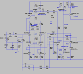
I'm looking at the diagram post #51
See, through D7 and C6, interference along the negative power wire penetrates directly to the base of transistors Q14,19,28,29 where they are amplified by this cascade and then mixed with the main signal.
Is this distortion sound made on purpose? Will this ever become normal for high-quality audio?
Last edited:
I don't mean to be too critical , but there are too many inconsistencies to cover (I ran the ASC). Simplified ,it goes (2 diode CCS/cascode/LTP/cascode/cascode/CM). separate reference for each. Zeners dissipate 35ma each and the VAS has a "shaky" current reference.It is unlikely that errors in topology will ever become a normal amplifier.
I won't mention the OPS !!! PS- Darlingtons nearly match Hfe of a typical EF3 , that is why they use them !
Simple is better (below). about the same deal , but with ONE reference for cascode/ltp and VAS (Q1-3) .... 13 devices-no diodes-no zeners.
OS
Attachments
- Home
- Amplifiers
- Solid State
- Morpheus ultra low THD