I think I figured it out!!
At least it works on the sim (B2 Spice). Its a little early in the morning to warm up the iron (4am). When something is on your mind, it just won't let go, so in the middle of the night a thought hits me.
I added a 1u Cap to ground on the upper crossing feedback wire on Rookie's circuit. BINGO. The 811 does not seem to hunt around any more. I suspect that I can lower that value, but its really late and I need to go to sleep. Look forward to a clean schematic to be posted soon.
Bernhard said:Netlist,
maybe you like to put my madness circuit on the sim too 🙄
The sim looks a little less mad than your drawing.

Did some efforts to simplify a few things, e.g. the layout but with respect to all the part names and numbers.
Used all LM6181, although I think you used some OPA-series for IC1/4/5/6?
I turned all the OP's with the +'s upwards.
Added R34 at the -input of IC5.
Changed R16 to 10k but I might as well change R18 to 1k ??
Guess the supplies of IC4 and IC5 are connected the wrong way in your 'madness', so I switched them.
Did a quick simulation and there seems to be some output, but with low amplitude.
/Hugo 😉
Netlist,
first: Cool that you do the sim !
second: Ooops !
It was deep in the night, and you're right, there are a few errors in my circuit...
### In all my schematics + supplys of all OPs shall be upwards.
### I forgot R34.
### 1k for R16 was correct, R18 was an error, must be changed to 1k.
Maybe try 1k for R17, R31, R32 R33.
Because with no R or with 100 ohm the basic OPs draw only 1/3 of the current and gain will go down.
Also may be try lower values for R Magic.
As JH stated, the gain of my circuit may not be so high...
I have a Ultracurve with digital-in as signal source, and it has a very high output, much more than a CD player.
Can you see the behavior of the idle current ?
May be supply current of whole amp with nospeaker load connected ?
Rookie said:Netlist,
Which simulator do you use?
Have you tried to simulate the schematic I posted?
1) http://www.spectrum-soft.com/demoform.shtm
2) Look at post #473/475 and let me know what you think.
/Hugo
jh6you said:Guys
As I have informed you earlier, my line stage is the unbalanced tube SRPP. Soon, I will try with BOSOZ having the balanced outputs.
JH
JH,
Did you run Miles balanced yet? Don't want to push you, but I would like to know how you managed to run your amp unbalanced? Hows the sound after a few days? And the DC?
Any improvements lately?
/Hugo - Out of coffee with all those late-night guys

Rookie..
I have simulated along with building a prototype based on your circuit. It seemed so have an oscillation until I added a cap to ground on the upper feedback leg. (Real world it had little gain and a great deal of heat - classic signs of oscillation) Stopped what seemed like the 811 from hunting in the really high frequency (In the megHz range). I used B2 SPice for the sims, and OPA541's instead of OPA549s. I also took the 541s out of unity and up to 2x and lowered the gain on the 811 to try to stop the "wiggles".
Now the problem on the sim (I have not made the change for real yet) is that the 1u cap is acting as a filter - about a 2.5dB rise from 20Hz to 20kHz, before it heads downward at about 30kHz. I was thinking of adding elements to build a steeper slope and raising its frequency to see if I can't get rid of the rise.
Maybe someone else has a better idea of how to get rid of it so I can ditch the cap. I hope so. The next step for me is to add two more 541's to get the current up. With it able to swing a total of almost 100v, along with 10A of current (20amp peaks), this will be a powerful amp for very few bucks.
Re: Rookie..
What about a 5 to 10pF in parallel with the feedback R or some twisted wires like JH did?
Like Nelson said: By a scope.
And post us some pics?
/Hugo
Sawzall said:
Maybe someone else has a better idea of how to get rid of it so I can ditch the cap.
What about a 5 to 10pF in parallel with the feedback R or some twisted wires like JH did?
Like Nelson said: By a scope.
And post us some pics?
/Hugo
Hugo,
Your schematic definitely differs from Nelson's original concept and my schematic, but it seems to work. I'm not sure if it is SuperSymmeetric,that's a question for Nelson.
Sawzall,
Have you tried to change the value of the resistor between the inverting inputs? It sets the open loop gain and has much to do with the stability of the amplifier. It's very likely that 100 ohms is not the optimal value .
Mosfet vs. bipolar
What is the better choice ?
A Mosfet with low Rsdon 0,01 ohm will loose only 0,0025V SD voltage 😎
That will be an advantage for high idle currents, but we don't have them here.
A bipolar transistor always looses 0,7V
But won't the gate of the Mosfet present a capacitive load to the OP ?
Also Nelson states that Mosfets will only work good with an output swing 5V below rails.
Netlist said:
Did you run Miles balanced yet? Don't want to push you, but I would like to know how you managed to run your amp unbalanced? Hows the sound after a few days? And the DC?
Any improvements lately?
Hi Hugo
Unbalanced-only so far. The signal line goes to one input and the ground line to the other input (grounded). Beethoven and Miles has pulled me more and more into a relaxation out of thinking about any thing else.
The absolute dc stays the same. Later, I have tried various values of R15 and R16 and found that 22k best fits together with R13/14 of 47k and R0 of 220. Only thing I have done is lengthening of the twisted lines (small pF) to about 10cm. It seems that the circuit is on the stable equilibrium condition upon the virtual ground assumed placed inside the magic resistor, even though the minor errors exist as the absolute dc of about 0.13V and the ignorable differential offset voltages. These minor errors might happen because I have used the components which do not matching at all.
Yesterday, I was rebuilding the amp into a box (portable). I however cut aluminum steels in wrong dimension as usual. When I finish this, I will try the balanced pre, Ariel speakers and the horn speakers of my main system, using much better interface lines and speaker cables.
JH
PS. Interested in the research on the op-only circuit and Madness circuit.
jh6you said:
Unbalanced-only so far.
I had very good results with R9/11 100ohm, R10/12 220ohm to ground,
R15/16 2.2k. But only when running balanced.
With lower values of R15/16 (2.2k-5k) you can give the amp a bigger source signal, higher values (10k-20k) don't permit that,
but the DC stays the same.
/Hugo
Madness works* always 😉
*works = Did not blow the transistors off the heatsinks yet...
I changed the 100ohm R17, R31, R32 R33 to 1k.
Also reduced the idle current, because I have still this poor PSU.
DC on pins 8 (+) and 4 (-) of OPs (NE5532) is +7,5V and -7,5V
DC on outputs of NE5532 is 0V.
DC on Amp output is still 0,01 V.
Without signal source connected I have 100Hz noise. This is new.
With signal source connected, there is no noise.
So the question is: What is the madness plug-in doing ?
I got some new AD811s🙂
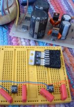
Will be building Rookie's/Netlist's circuit, pic below is the progress so far, I will be using OPA458s rather than 9s, as I have more spare in case I blow any up!
Above the breadboard is my regulated 15-0-15 psu that I will be using to power the circuit to start with, for testing.
Will be building Rookie's/Netlist's circuit, pic below is the progress so far, I will be using OPA458s rather than 9s, as I have more spare in case I blow any up!
Above the breadboard is my regulated 15-0-15 psu that I will be using to power the circuit to start with, for testing.
Attachments
Netlist said:
I had very good results with R9/11 100ohm, R10/12 220ohm to ground,
R15/16 2.2k. But only when running balanced.
With lower values of R15/16 (2.2k-5k) you can give the amp a bigger source signal, higher values (10k-20k) don't permit that,
but the DC stays the same.
/Hugo
I am sure of your good results. By the way, what happens when it runs unbalanced? And when you have the lower R15/16 (with R9-12), is the DC unstable? Your info would help my further(?) experiment after testing the balanced run this weekend.
JH
pinkmouse said:
AD811s + OPA458s
Look forward to hearing from you about the results. Good luck.
JH
interesting result
of changing the magic resistor on the sim. Increasing the value to 400Ohms eliminated the rise that I was getting from the cap that I had put in place. I wonder if this is true in real life? Does the value of R(0) effect frequency response? (I guess in the extreme it would, since it effects bandwidth product).
None the less, increasing it did not totally eliminate the need for the cap. Just made the plot more interesting to look at - nice squarewaves at really high values. I have to tell you that I have learned a great deal from playing with this - it got me re-interested in the hobby and sitting down and studying the books.
This is going to be a long week at work - Tax time, dammit. Pray for me, and I hope to get back to playing with this next weekend. Perhaps someone will have solved the circuit by then.
New progress 
I put the scope across one bias resistor to see what happens there.
One input of the amp grounded.
On the other side the 1k resistor at the input of the LM6181 grounded also, and only the madness part of the circuit fed with the input signal.
The scope shows something like a double frequency sinewave across both, the upper and the lower bias resistors.
This is very good news I guess, because also the connected speaker remains silent.
That means, there is modulated idle current flowing, which does not appear as an output signal.
Here is a new drawing: ( But I use NE5532 double OPs instead of single OPs)
- Status
- Not open for further replies.
- Home
- Amplifiers
- Pass Labs
- Monolithic SuperSymmetry with Current Feedback