The signal across the bias resistor is small and I can't find my probe... 🙁

Any comments ? 🙄
The amp sounds the same to me with normal and with madness operation
Any comments ? 🙄
The amp sounds the same to me with normal and with madness operation
I can be brief here. Run the amp balanced! I connected the amp unbalanced (for the first time) and the strangest things happened. No doubt everything is well connected. I'm not saying the amp can't be run unbalanced. You proved it, JH. But in my setup and circuit and with mosfets it doesn't perform well vs. very well balanced. (Mainly oscillations) It gives me 5 to 10mV absolute Dc and +/-35mV differential DC. I can live with that 😉 😉jh6you said:
what happens when it runs unbalanced? And when you have the lower R15/16 (with R9-12), is the DC unstable? Your info would help my further(?) experiment after testing the balanced run this weekend.
JH
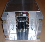
This is the very good working balanced Mosfet version: see pic below. Note the 4ohm load (my two speakers in parallel,). Didn't build the stereo version like you. Of course anyone can jump in to make improvements.
Bernhard said:The signal across the bias resistor is small and I can't find my probe... 🙁
Any comments ? 🙄
Difficult to say, but to me this doesn’t look like a 'clean' signal.
What do you mean by bias R's? R3/4/6/7?
Where or what do you connect, disconnect to switch the Madness on or off? R17/31/32/33?
/Hugo - thinks Bernard is really fearless

Attachments
OK circuit together, but it's not working yet🙁
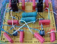
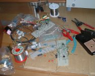
In the pic below you can see the finished breadboard, with the X in the middle bottom and the two parallelled 15Ohm resistors as the load.
When I first plugged in one of the OPAs was oscillating I assume, as it heated up quickly, so I added the .1uf to ground as per Sawzal's idea. This killed the heating, but after I applied a signal I get no output. So, I think I will check all the devices, and then retry maybe using some of Netlist's ideas.
Attachments
Netlist said:
Run the amp balanced! I connected the amp unbalanced (for the first time) and the strangest things happened. No doubt everything is well connected. I'm not saying the amp can't be run unbalanced.
Difficult to say, but to me this doesn’t look like a 'clean' signal.
What do you mean by bias R's? R3/4/6/7?
Where or what do you connect, disconnect to switch the Madness on or off? R17/31/32/33?
Ever since I run my amp unbalanced and it does not make any problem.The signal is small and I do not have a probe so the cables pick up noise...
Yes, R3/4/6/7.
I have seperated the inputs of the madness part of the circuit from the inputs of the normal part.
I disconnected the wire that goes from amp input to R20/21, so normality/madness become independent.
But there is always the idle current from all three OPs/each side.
I will make new measurements, it was AC coupled and...
pinkmouse said:OK circuit together, but it's not working yet🙁
Hi, pinkmouse
I never build the circuit, only sim.
Why all those caps around your board?
Where did you get those breedboards? Looks like you can do the "Turbo-DIY" with them. 😎
/Hugo - will post a picture of his "mess"

Netlist said:
Hi, pinkmouse
I never build the circuit.
Well that makes two of us then!😉
Why all those caps around your board?
The four on each end are for decoupling the power rails, as suggested in the device app notes, and the two in the middle run to ground from the X resistors as suggested by Sawsal.
Where did you get those breedboards? Looks like you can do the "Turbo-DIY" with them. 😎
I got them from a friend who found a load of bits in a cupboard he used for electronics when he was a kid.
I now have the circuit working, (badly), but I think there may be a connection error somewhere as it is distorted and single sided!

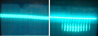
The pic below shows the input and output:
Attachments
Guys...
Wanna know, what is real madness ? 😡
My PSU is already in current limiting mode and gives big fat 2,2Vpp triangle spikes with 50Hz repetition rate 😡
**** *** !!! 😡
This was not visible in the first measurments, because one side of the bias resistor is on the rail...
Now I tried to see whats going on on the madness OP supply wires, and I was wondering and wondering...
Ramp all over the screen... 😕
But the amp seems to be very good. Even this worst case PSU gives a clean output signal. 😎
Now I must build a PSU
Fear no
Bernhard said:
That's true, but your amp differs from mine. Post #427 is your final() one. Post #502 is my final() one. BTW, did you ever try your amp balanced? If yours runs good with both balanced and unbalanced inputs this makes it a better amp in that way. When mine is unbalanced and not oscillating, I keep thinking the balanced version sound a lot better.
To Sawzall:
Because I couldn't make it work like this.Why the connections on the inverting inputs to the 811 to 811 wire? Why not take them to ground?
/Hugo - Guess this is the most experimental thread ever seen on this forum.
BTW, guys, we exceeded 500 posts! Time for a drink!

Also thinks Nelson lost track in this thread.
Bernhard said:
Wanna know, what is real madness ? 😡
You won't end in Texas, but in Madland 😉
/Hugo
Maybe I need a break
There are a few things, I do not understand, has nothing to do with the madness:
When I feed the amp with sine signal:
Across the bias resistors there is a complete sine wave, why ? 😕
I always thought, the upper part carries only the positive halfwave, and the lower part only the negative halfwave.
Can someone please help me with this basic question ? 🙄
Without the load connected, I also cannot measure anything across the bias resistor.
Sine current flows only through the bias resistor, if sine current flows through the load.
Bernhard said:Across the bias resistors there is a complete sine wave, why ? 😕
Bernhard
Reference: your bias resistors R3/4/6/7 and emitter resistors R/1/2/5/8.
If there is a fluctuation of current through the emitter resistors, a fluctuation of current through the bias resistors also happens. The circuit is designed to work so, IMHO.
Wishing your good results.
JH
PS.
For your info: If we increase the bias resistor values greater and greater, the transistors work for the current boosting bigger and bigger. This will however increase the dc current making the amp hotter and hotter. Or vice versa.
Bernhard
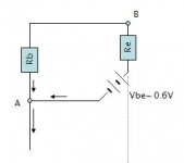
Take a look at the attached figure.
If a voltage (current) fluctuating across Re happens, the voltage (current) across nodes A and B also fluctuates, and then the voltage (current) across Rb fluctuates.
Hoping this would clarify the question...
JH
Take a look at the attached figure.
If a voltage (current) fluctuating across Re happens, the voltage (current) across nodes A and B also fluctuates, and then the voltage (current) across Rb fluctuates.
Hoping this would clarify the question...
JH
Attachments
jh6you said:Hoping this would clarify the question...
JH
🙁 🙁 🙁
If there is 1,3V on the base, that means only +/- 0,65V swing is permitted, otherwise the transistor goes to nonlinear (<0,65V) mode.
😕 😕 😕
If we reduce Re from 1 to 0.22, we would see less fluctuation of voltage across Rb.
I use 0.22 for the amp going into an aluminum case.
JH
I use 0.22 for the amp going into an aluminum case.
JH
JH,
my scope told me that
the voltage across the bias resistor is only a complete sinewave @ low levels.
Somewhere the sine starts clipping @ higher levels and @2V input it is only halfwave.
IMHO the beginning of clipping indicates leaving classA.
This clipping does not mean clipping or visible distortion on the output...
I don't understand it completely yet, why it is a full sine @ low levels, but time will tell...
my scope told me
that the voltage across the bias resistor is only a complete sinewave @ low levels.
Somewhere the sine starts clipping @ higher levels and @2V input it is only halfwave.
IMHO the beginning of clipping indicates leaving classA.
This clipping does not mean clipping or visible distortion on the output...
I don't understand it completely yet, why it is a full sine @ low levels, but time will tell...
Here is a picture showing the amp on progress into a case (rear view). I could restart the listening this weekend--with the balanced input.
JH
PS. The case is not a brand new, used materials. This is why the heat sink is this big. And there are many old bolt holes. 🙂
JH
PS. The case is not a brand new, used materials. This is why the heat sink is this big. And there are many old bolt holes. 🙂
Attachments
Bernhard said:
why it is a full sine @ low levels, but time will tell...
Let's share the info about the figure, later. 😉
JH
jh6you said:Here is a picture showing the amp on progress into a case (rear view). I could restart the listening this weekend--with the balanced input.
Joooohooo....looks like you cleaned up the mess.
Nice.
/Hugo - his amp will never be boxed.

more learning happening here
I asked:
The answer is yes. National's note OA-20 is suggested reading - Current Feedback Myths Debunked. As I understand it, the inverting input is trying to be driven to zero current by the output. R(o) is part of the feedback loop as it goes all the the way around the circuit. R(o) does many things, but one of them is affect the impedence of the circuit, and in that role, it changes the gain of the amp, stability, and bandwidth, thus response of the amp. I won't pretend to understand it all - but this note reminds me that although it does it differently, an opamp acts like an opamp, and the ideal opamp rules apply..
You can safely ignore me as a blunder my way thru..
I asked:
Does the value of R(0) effect frequency response?
The answer is yes. National's note OA-20 is suggested reading - Current Feedback Myths Debunked. As I understand it, the inverting input is trying to be driven to zero current by the output. R(o) is part of the feedback loop as it goes all the the way around the circuit. R(o) does many things, but one of them is affect the impedence of the circuit, and in that role, it changes the gain of the amp, stability, and bandwidth, thus response of the amp. I won't pretend to understand it all - but this note reminds me that although it does it differently, an opamp acts like an opamp, and the ideal opamp rules apply..
You can safely ignore me as a blunder my way thru..
- Status
- Not open for further replies.
- Home
- Amplifiers
- Pass Labs
- Monolithic SuperSymmetry with Current Feedback