if using fixed biasing, regulating the screens required regulating the grid bias supply right?
I'm not sure about required, but it would probably be wise... if you regulate the screen, and not the bias, as line voltage drops your bias drops but the screen stays up, so current goes up. Especially if the plate isn't regulated, screen dissipation can get too high.
A lot of people last winter were talking regulated supplies and making little PCB's for various regulator designs. So, at that time, I was thinking about building an amp w/ this board, and regulating everything in the power supply. But, I don't know anymore. That's a lot of work and heat sinks. Results probably aren't worth the effort.
If anyone else is thinking about it, let us know.
If anyone else is thinking about it, let us know.
I will likely build something with regulated bias and screen supplies. It is my belief that this is the correct approach, at least when playing with sweep tubes. Regulating the plate supply on a pentode amp may be a waste of time and output power.
I started down the road towards a monster, but it will lie dormant until maybe mid February. I work in an IC design team. We taped out two chips which will arrive during Christmas break. It will be full speed ahead when I get back from a 2 week trip to cold country.
I'll try to post a picture of the beast before I leave town.
working with TV sweep tubes, i find that using a 4diode center tapped FWB or a voltage doubler is the way to go since the screen voltages will be less than half of plate voltage...
I will likely build something with regulated bias and screen supplies.
Any particular regulator circuits you like? That's sort of where I got hung up last year.. Reading through all the threads on the subject.
The LR8 circuit below I have used before with a preamp power supply.
However, I would like some gas tube glow.
The bias circuit should be fine with a simple gas tube shunt circuit (substitute for zener below).
Has anyone used a transistor as pass element in a gas tube referenced supply (i.e. substitute a gas tube for the zener)?
However, I would like some gas tube glow.
The bias circuit should be fine with a simple gas tube shunt circuit (substitute for zener below).
Has anyone used a transistor as pass element in a gas tube referenced supply (i.e. substitute a gas tube for the zener)?
Attachments
Any particular regulator circuits you like?
I have seen plenty of rather complicated closed loop regulators, and I may indeed experiment along those lines, but I have been using a rather simple circuit known as a capacitance multiplier since the 1960's.
A closed loop regulator like the Maida must be well designed to avoid instability when connected to a capacitive load, and supplying a varying current load like a class AB amp. It can and has been done, and is the right choice for a plate supply due to its low output impedance.
I am interested in regulating the screen and bias supplies. A very low output impedance is not needed, neither is .01% regulation. What we need is a stable source with good regulation that can't be driven into convulsions when the Big Dumb Blonde One plugs in his guitar and drives the amp about 20 db beyond clipping. 🙂
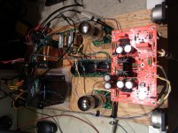
I have one of Pete's big red boards set up as a 125 WPC HiFi amp, but I have used it for a (very loud) guitar amp several times. I am using the screen regulator as Pete designed it, but I had to add a zener to the bias circuit to stabilize the bias.
I am running about 600 volts of unregulated B+. I set the bias at 35 mA for a dissipation of 21 watts on 24 watt tubes. The dissipation goes up when you crank the amp, but the average stays in the dark plate zone even when playing guitar.
I have seen the amp show a dull red plate on one or two tubes (always the same two) on several occasions, sometimes while playing at low volumes. The redness follows the tubes when they are moved around. The red plating seems to occur in the late afternoon, when the line voltage is LOWEST. WTF???? Investigation occurred....
According to the new GE smart electric meter on our house the line voltage varies from 238 to 244 volts, about 2.5% overall. However the unregulated B+ on many of my amps can vary up to 5%. The raw negative bias voltage varies almost 10%!!!! WHY????
In the late afternoon everyone's AC units are running hard, even in "winter". People are cooking dinner, and running one or more TV's and computers. The line voltage reads 238 to 240, but that isn't the problem. The line voltage is highly distorted with ovbious flat topping on the sine wave. Transformer saturation effects can be seen too. I have measured over 10% distortion on our power line. On Saturday morning, when I usually tinker with amps, the line voltage is 242 or 243 volts, but the distortion is under 5%.
The voltage produced by a capacitor input full wave rectifier fed with a sine wave will vary according to the load, the rectifier, and the amount of capacitance in the first filter cap. In theory the voltage will be 1.414 times the RMS voltage. This is ONLY true with ZERO load current and a perfect sine wave.
The diode only conducts for a brief instant at the very peak of the sine wave since the cap is charged to 1.414 times the RMS voltage, and the sinewave only touches this point at the peak. As the load current is increased charge is removed from the cap during the time the diodes are not conduction, so the diodes start conducting earlier in the cycle. The charge in the cap is no longer constant (ripple) since it is now drained and replenished during each cycle. The AVERAGE voltage is now lower. The higher the load on the rectifier system, the lower the average voltage will be. The power supply output voltage after additional filtering will be this average value, minus resistive losses.
Up until now we have assumed a sine wave input. What if there are 9,945,442 electronic devices all connected to your power grid without PFC (power factor control) all consuming the bulk of their power for a few mS right before the peak of the sine wave. This area of the sine wave gets erroded. Most of the electronic devices in the US do not have PFC. Your non PFC tube amp is competing with all these other devices for its fair share of electrical power for those same few mS.
The plate supply in my version of Petes big red board sees a 175 mA load at idle and goes to 600 mA or so at full crank. It's conduction angle is large, and increases as the volume is cranked. The voltage varies from 595 to 620 volts at an idle, and drops as low as 565 volts when the guitar is plugged in and cranked.
The bias supply is on a seperate transformer winding. It has a very light and nearly constant load. The rectifier in the bias supply only conducts for a small period of time. The voltage output of the bias supply is almost completely dependent on the peak value of the sine wave, which is highly dependent on the distortion caused by non PFC loads, INCLUDING The amps own plate supply! So, when the power line distortion goes up, the sine wave's peak gets clipped off and the output voltage of the bias supply DROPS, pushing the output tubes harder into conduction.
Amps with the bias supply on a seperate winding are affected more than amps with a bias tap, and amps with a seperate transformer for bias are worse case.
If I was building a triode amp, or any other design where the tube current is highly dependent on the plate voltage, I would consider regulating the plate supply.
For this design I am currently experimenting with sweep tubes. They have a rather sensitive control grid due to a high Gm. A few volt bias change can cause a big change in plate current, and with a B+ over 600 volts a few extra mA can melt tubes. The screen also has a strong influence on plate current, and will be regulated as well. This may not be needed with conventional audio tubes, and as Pete stated, some audio tubes like the EL34 prefer a somewhat sloppy screen voltage. Mullard recommends a 1K resistor in series with the screen in the EL34 data sheet. Make it a 2 watt resistor if you plan on repeated trips into clipping!
I plan to use a circuit similar to the screen regulator in Pete's big red board. It is Q1 and the associated components. Pete added R1 to lower the dissipation in the mosfet. Do not eliminate this resistor (a lower value is OK). It is needed for peak current limiting at turn on, otherwise the surge can blow the mosfet. The regulation can be improved by replacing R33 with a CCS. This removes output voltage variation caused by the zener impedance. Using a film cap in place of, or in parallel with C22 improves the high frequency noise. So can another (RC) pole of filtering in series with R46. D6 can be omitted if your mosfet has built in gate zeners.
For the bias supply I plan to use the same circuit with all the caps and diodes turned around and a P channel mosfet.
Has anyone used a transistor as pass element in a gas tube referenced supply (i.e. substitute a gas tube for the zener)?
I have used a VR tube in the same circuit described above (Petes circuit used for example).
Do not put a large value cap directly across the VR tube, that will make a relaxation oscillator. I use a .01 uf cap. C22 in Petes drawing.
Several VR tubes can be wired in series for the required voltage, and you can tap off of each one with its own follower. As before a CCS will improve the regulation.
I prefer a mosfet or vacuum tube follower. A mosfet provides the best regulation due to its high Gm. A vacuum tube has glow appeal, and is generally more forgiving of accidental short circuits that tend to rearange the molecular structure of silicon devices. I avoid BJT's in circuits that draw a varying current, because they draw base current proportional to the load current. This affects the current through the zener / VR tube string, which also affects regulation.
In my previous post I assumed that the readers know where to find Petes circuit. It is here:
DCPP Amp
I was going to post a picture of my latest experiment last night, but I realized that it now consists of too many pieces scattered in too many places. Back in post #130 I had to grab everything that was outside when it all got rained on.
In post #124 I said this:
The answer is 16! I was outside drilling a piece of perf board to accomodate 16 sockets for the 13GB5's when the rain came. Later that afternoon I finished the drilling, and that evening I started wiring up the heaters. I haven't had time to go further, and won't until sometime in February.
I am building a breadboard that will use two of Petes driver boards, and up to 16 13GB5's in two stereo sets of 8 tubes wired as PPP banks of 4. Initial testing will be with a "normal" set of 4 tubes (push pull stereo). Additional tubes will be added until, it blows up, I blow the bench breaker, or I reach 500 WPC!
All testing will be done using bench power supplies. I am doing this to experiment with the possibility of wiring together multiple small OPT's to see if a big amp can be built with reasonably sized OPT's. I have a pair of big OPT's for comparison.
If success is achieved the final build may use different tubes. The 13GB5's are currently cheap, and I don't mind melting a few. I have 30 or so 35LR6's which are about equal to a pair of 13GB5's. I have extracted 250 watts from a pair at the edge of redness. I have some 6LW6's which are even BIGGER!
The final power supply will be made using one or more toroids. As Pete suggested earlier a FWB can be wired across the full secondary for B++ and the center tap can be used for B+. The BFT mentioned in post #127 looks good for a B+ of 275 volts and a B++ of 550 volts.
In post #124 I said this:
It contained 150 13GB5's, 50 sockets, and 50 plate caps. Now the only question is how many of these guys do I connect together!
The answer is 16! I was outside drilling a piece of perf board to accomodate 16 sockets for the 13GB5's when the rain came. Later that afternoon I finished the drilling, and that evening I started wiring up the heaters. I haven't had time to go further, and won't until sometime in February.
I am building a breadboard that will use two of Petes driver boards, and up to 16 13GB5's in two stereo sets of 8 tubes wired as PPP banks of 4. Initial testing will be with a "normal" set of 4 tubes (push pull stereo). Additional tubes will be added until, it blows up, I blow the bench breaker, or I reach 500 WPC!
All testing will be done using bench power supplies. I am doing this to experiment with the possibility of wiring together multiple small OPT's to see if a big amp can be built with reasonably sized OPT's. I have a pair of big OPT's for comparison.
If success is achieved the final build may use different tubes. The 13GB5's are currently cheap, and I don't mind melting a few. I have 30 or so 35LR6's which are about equal to a pair of 13GB5's. I have extracted 250 watts from a pair at the edge of redness. I have some 6LW6's which are even BIGGER!
The final power supply will be made using one or more toroids. As Pete suggested earlier a FWB can be wired across the full secondary for B++ and the center tap can be used for B+. The BFT mentioned in post #127 looks good for a B+ of 275 volts and a B++ of 550 volts.
New KT88 triode breadboard
OK, got the revised KT88 triode on the breadboard.
Using the "100W Marshall" power transformer 40-18046, and the A-431S OPT (both from Triode Electronics).
B+ 566V
Driver B+ 281V
Biased at 45mA/tube (25W dissipation at idle per tube)
Some quick measurements:
Frequency response @ 1W: -3dB @ 6Hz and 105kHz
1W THD: 1kHz 0.008% (!), 20Hz 0.07%, 20kHz 0.06%
5% THD: 1kHz at 18V into 8 ohms (40W), 20Hz 8.5V (9W), 20kHz 18V (40W)
Zout: 0.8 ohms - I'm thinkin' electrostats!
1.5V RMS in for full power out
Yes, there is significant global NFB in use to get this.
Square wave is perfect, even at 20kHz.
Driver is using 12HL7's, 10k plate load, 85V screen (85A2 VR tube) - otherwise pretty much the same as on the web page.
More to come... works well enough that I think its time to make a pair of chassis.
Attachments
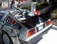
It's only natural that the next step will involve high tension lines...
Power lines are just too old school......I'm thinking of something from the future.....Mr. Fusion filtered through a Flux Capacitor. You see, I know where Doc Brown parked this Delorean....It hasn't been started since 1985, but maybe if we push it up to 88 MPH and drop the clutch.....
Just think about it 1.21 JIGGOWATTS!!!!!!!!!
Attachments

Pete -- wow that was fast! And Mr. Godzilla's "scales" look suspiciously like glued on holly leaves.
George, the only "goodies" I got with my big toroids was two gaskets and a wiring diagram in a separate envelope. Mine did not come in the original box so I guess I missed out...
George, the only "goodies" I got with my big toroids was two gaskets and a wiring diagram in a separate envelope. Mine did not come in the original box so I guess I missed out...
George, the only "goodies" I got with my big toroids was two gaskets and a wiring diagram
I got one gasket and the diagram in the envelope. The toroid was wrapped up in bubble wrap. There were several knobs, a small PC mount transformer and a tube shield. The small transformer and the shield were both flattened by the toroid. No explanation for the spare parts.
And Mr. Godzilla's "scales" look suspiciously like glued on holly leaves
There was no CGI when Godzilla was made. Some of the younger generation believe that the moon landing missions were all faked hollywood style. My answer to them is to watch one of the original Star Trek episodes or a 1970 vintage Sci Fi movie.
OK, got the revised KT88 triode on the breadboard.
Any idea how much current is flowing in the 12HL7's. My boards work great from 300 to 650 volts, but distort badly below 290 volts, and cease to function below 280 (no output). Granted I haven't even tried to figure it out, and I am running different tubes at a higher current. So far I haven't done much exploration at the lower end of the power supply knob.
Yes, there is significant global NFB in use to get this.
I had a KT88 triode breadboard running for about a year using a totally different driver. Of course it measured best with feedback, but I liked the sound best with no feedback at all.
In case anyone can find them, the killer tube for this application is the 7403 or the 3D21WB (not any other 3D21 type). They have a 40 watt plate with a 4KV maximum rating, 850 volt screen grid rating, 10 AMP peak cathode current rating (awesome transient delivery) and nice looking triode curves.
http://www.mif.pg.gda.pl/homepages/frank/sheets/131/7/7403.pdf
I ran them in my triode KT88 amp for a while and think they sounded better that the EH KT88's they replaced (WARNING different pinout). I wanted to try them in the big red board and never did, but they will get tested with this board.
Tubelab, thanks for the regulator info.. that was a great post.. I am definitely wanting to keep it simple, and think I'll go w/ a version of Pete's circuit too.
Pmillett, any plans to build the 807 version? If not, I'll probably be back asking for a bit of help figuring out feedback in about a month 🙂. I'll keep it documented to help others. I may find out it's not worth the effort in the end, but I want to try something other than triodes (or triode connected whatevers).
Pmillett, any plans to build the 807 version? If not, I'll probably be back asking for a bit of help figuring out feedback in about a month 🙂. I'll keep it documented to help others. I may find out it's not worth the effort in the end, but I want to try something other than triodes (or triode connected whatevers).
In case anyone can find them, the killer tube for this application is the 7403 or the 3D21WB (not any other 3D21 type). They have a 40 watt plate with a 4KV maximum rating, 850 volt screen grid rating, 10 AMP peak cathode current rating (awesome transient delivery) and nice looking triode curves.
I just picked up a dozen 3D21B on eBay for $50. Lower plate dissipation than the WB but it might be interesting anyway. I wonder how far they can be pushed...
Merry Christmas George!

Last edited:
Pmillett, any plans to build the 807 version?
I plan on at least breadboarding it. I think it should work with everything the same as for the KT88 triode... who knows, if it works well enough maybe I'll build that on a chassis.
Pete
I grabbed 4 off ebay earlier, but I don't know if I got the B or the WB.
I can't find a datasheet on the B.. What's the difference?
I can't find a datasheet on the B.. What's the difference?
well, if anyone else grabbed some from the guy who had them listed as 3d21b 3d21wb 40 watt, I just got confirmation they are NOT the WB's, and have the small plates.
- Status
- Not open for further replies.
- Home
- Amplifiers
- Tubes / Valves
- Mono push-pull driver PCB