I will encourage the builders of the Modulus-86 to post their findings here.
In other news: The AP SYS-2712 I have access to does indeed have the IMD option, hence, it should be possible for me to measure the 19k:20k 1:1 IMD and 60Hz:7kHz 4:1 SMPTE. Yay.
~Tom
In other news: The AP SYS-2712 I have access to does indeed have the IMD option, hence, it should be possible for me to measure the 19k:20k 1:1 IMD and 60Hz:7kHz 4:1 SMPTE. Yay.
~Tom
What I would be most interested in hearing is from those who already have and are using LM3886 based amps, and who build this one up (in the same power levels, please) and relate their entirely subjective reactions.
My current system (bi-amped) runs LM3875 for the Fullrange and LM3876 for the Woofers. PSU is (separate case) SMPS at ±32Volts.
I have on the bench ATM a new amp running 4x LM3886 modules, loaded on eBay XY PCB's. PSU (separate case) is 2x 300VA torroids with 8000uF on each rail. Rail Voltage 34Vdc regulated down to 28Vdc, at the amplifers.
I have just ordered 4 of Toms Modulus 86 PCB's to replace the LM3886 modules. I'll run the LM3886 for a while before I swap to the Modulus 86 and reort back with my subjective impressions.
As far as cost, I could if asked quote a price on just the assembly of this amp, assuming that all the chassis and parts were prepared - I think that it would be a bit rich for most folks, just because of the hours wrapped up in the raw labor. So, the cost of the boards while not the lowest I've seen here on DiyAudio, isn't all that high compared to the cost of the rest of the parts. Add in the time and cost for design and development..
I thought the PCB cost was fair considering the the level of R&D involved.
MY PSU cost WAY more than the Amplifier. The better the PSU the better the potential outcome for the Power Amp so this thing is well over engineered.
2x 300VA Torroids
16x MUR860's
4x 8000uF chassis mount caps
Thank you very much for your order. Your boards will ship tomorrow morning (US Pacific time).
~Tom
~Tom
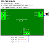
Mmm, stopping shield at the chassis is one option. So is continuing shield to the board if one's concerned about noise pickup within the chassis. The latter makes sense for helping get the most out of a fairly low noise amp like the Modulus-86 but does want a board which distinguishes between chassis/shield/earth/green wire ground and power/signal grounds off the secondary. I think that's the case here---the circuit topology diagram has a different ground symbol on the signal input than the power input or speaker output---so most likely it's a labelling issue with the figures in post 86.
If you want the EMI/RFI filter to work, you have to provide a ground for the RF return. If you prefer that XLR Pin 1 connects to only the EMI/RFI filter and the chassis, you can pluck a wire link off the board. However, you do need to ensure that the common-mode voltage of the input is within the common-mode range of the input amp - just as you would for any other differential input.
At the very least, continue the shield (connected to Pin 1) all the way to the input connector as Twest explains above.
I'll update the figures to rename the Pin 1 ground on the board. That should clear up some of the confusion.
Much of the optimization of the board involved optimizing the various grounds to ensure the best signal integrity possible. Sadly, my figure labeling skills aren't up to par with my circuit design skills... 🙂
~Tom
Last edited:
I'll go with:
Neil Muncy
Henry W. Ott
Jim Brown
Bill Whitlock
Keith Armstrong
Tony Waldron
and
Audio Engineering Society standard
AES 48
Neil Muncy
Henry W. Ott
Jim Brown
Bill Whitlock
Keith Armstrong
Tony Waldron
and
Audio Engineering Society standard
AES 48
Last edited:
AES 48**) is OK and works well IF all devices in a setup adhere to it. But even then, there might be excessive shield currents provoking shield-induced noise. Hybrid-grounded cables help best (ferrite bead to pin 1 and ring capacitor to connector shell, Neutrik offers connectors).
On-board EMI-Filters are sort of a no-go in AES 48, these must be right at the input connector, as close to the chassis as possible.
IME, unless you're really out of luck none of these extreme precautions are necessary in most domestic (read: low complexity) environments.
**) Assuming a metal chassis, all connector pin 1's go directly to the chassis, AND the circuit GND goes to the chassis, using a true single wire connection. Earth GND must go to the chassis as well unless one can build Class-II compliant. This of course might challenge the CMRR of the input differential receiver.
http://www.kirkeo.org/sites/default/files/pdfs/node15/aes48-2005-f.pdf
Last edited:
Neil Muncy wrote the paper in 1994/95 that then became AES 48. Now 20 years later, isn't it time that designers got up to speed?AES 48**) is OK and works well IF all devices in a setup adhere to it.
Shield Current Induced Noise (SCIN) is a different problem and a good reason for buying very symetrical balanced interconnect cables.But even then, there might be excessive shield currents provoking shield-induced noise.
Experts differ on this. Some say always, some say only if really needed and some say never use a hybrid shield connection at the receive end.Hybrid-grounded cables help best (ferrite bead to pin 1 and ring capacitor to connector shell, Neutrik offers connectors).
I would use the type , that is seen in many THAT circuits.On-board EMI-Filters are sort of a no-go in AES 48, these must be right at the input connector, as close to the chassis as possible.
True, balanced interconnect systems are very robust and problems aren't that common.IME, unless you're really out of luck none of these extreme precautions are necessary in most domestic (read: low complexity) environments.
.......................................
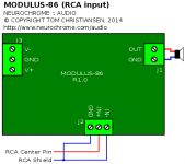
I followed THAT's recommendations for the input filter and connections. If you can find a connector that has the filter components built-in, just use that and don't populate the filter parts on the board.
I do agree that the best place for the filter components is right in the connector as this minimizes the EMI entering the enclosure. Sadly, however, I don't have control over what my customers do there, so I put the components on the board so at least the clicks and pops from motor switches and annoying GSM cell phone bursts will get filtered out.
I did expect that more savvy builders to move the EMI/RFI filter to the connector and terminate Pin 1 as they see fit.
~Tom
IME, unless you're really out of luck none of these extreme precautions are necessary in most domestic (read: low complexity) environments.
That's my experience as well. However, playing with a pair of Parasound A23 power amps, P3 preamp, and (forget model number) CD player on a pair of Dali Suite 2.8 speakers, my subjective experience was that the sound cleaned up considerably when using the differential connections.
Using differential signalling takes the ground connection between the different components out of the signal path. This improves the signal integrity, resulting in better sound as the various noise components present on the ground are rejected by the CMRR (90+ dB in case of the MOD86). The differential I/O on the P3 and A23 are discrete opamp based solutions using 1 % tolerance resistors. They are trimmed, but I doubt the CMRR is better than 60 dB. Still, that's enough to make a significant audible difference.
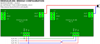
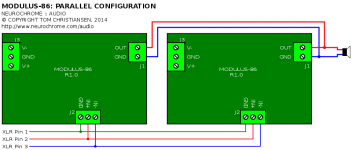
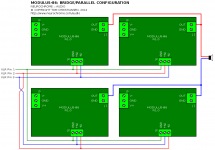
So even in residential environments, significant benefits can be had by using differential signalling, which is why I implemented it on my Modulus-86 (and DG300B). In case of the MOD86, it also allows for easy bridging. All you need to do is to swap a pair of wires and you're in business.
~Tom
PS: Thanks for the link to AES48-2005. I really appreciate it when folks back their claims up with data and facts. Yay! 🙂
Last edited:
How so? I find no text about filters in the linked doc.On-board EMI-Filters are sort of a no-go in AES 48, these must be right at the input connector, as close to the chassis as possible.
Frequency response measurements
Not to change the subject, but I got curious and measured the frequency response. That was a bit interesting as the LF -3 dB frequency is 1.6 mHz. That's one cycle every ten minutes... Needless to say, I started the analyzer and went to bed... 🙂
Now the HP3563A only goes to 100 kHz, so to get the HF -3 dB point, I resorted to a network analyzer. Hence, the units are different between the two measurements. The LF measurement is in dBV and the HF measurement in dB (gain). Thankfully, 3 dB is 3 dB, so life is good.
The bandwidth of the Modulus-86 extends from 1.6 mHz to 140 kHz (-3 dB). The amplitude variation within the audio band is ±0.04 dB. That's approaching the measurement tolerances of the network analyzer.
~Tom
Attachments

Last edited:
I double up the input filtering...........................
I do agree that the best place for the filter components is right in the connector as this minimizes the EMI entering the enclosure. Sadly, however, I don't have control over what my customers do there, so I put the components on the board so at least the clicks and pops from motor switches and annoying GSM cell phone bursts will get filtered out...............
A 47pF at the back of the input socket to attenuate the differential interference at the entry to the equipment.
Due to insulated barrel to Chassis, this does nothing for common mode interference. But it is at least an improvement over letting interference a free entry along the internal cable. This lonely capacitor relies on source impedance and cable inductance to generate an actual R+L C low pass filter.
Then at the receiver PCB, I fit a RC low pass filter. Generally around 0.68us
I can lay an active mobile phone anywhere on, or around, my audio gear and get no audible interference.
Recently I converted an old stereo power amplifier during a re-wire and update.
I used a pair of XLR sockets as the unbalanced inputs.
I soldered three 47pF around the three pins and connected Pin1 to shell which was bolted direct to the metal chassis. This gave a bit of differential mode attenuation and a bit of common mode attenuation.
Having used this for a few months I could not hear any downsides to the two extra capacitors (pin1 to pin2 and pin1 to pin3) as well as the usual pin2 to pin3 described earlier.
This arrangement uses a 47pF directly from signal Hot to Chassis with no apparent loss of audio performance.
I have not yet fitted common mode filtering to the speaker outputs, but I do have a differential mode filter here. I use the Pi version of the Thiele Network.
Last edited:
I found myself mulling about input filtering as well. To prevent the RF from entering the chassis, the filter must be located at the connector - preferably integrated into the connector. However, to filter the interference generated within the chassis or entering the chassis through other means (vent holes, for example), a filter on the board is needed.
The most effective filter at the connector is likely going to be a ferrite bead draped over the wire right where it connects to the solder cup. You can back it up with a capacitor to Pin 1 if you're paranoid (or need the gear to work well in high-interference environments). The capacitor will need to be on the "inside" of the ferrite bead.
For filtering the EMI that is present within the chassis - either by radiation within the chassis or by entering through holes in the chassis - the EMI filter on the Modulus-86 board will be effective, as long as it is provided with a low-inductance path to Pin 1 of the XLR connector.
My recommendation will be to use a shielded cable from the XLR connector to the board. Terminate the shield in one end to Pin 1 of the XLR connector and the other end to the SHIELD connection on the board (I'll rename it in the figures). This will provide the lowest inductance return path for the RF energy trapped by the EMI filter. Also, connect Pin 1 to the chassis at the connector.
If one wants to be 100 % AES48-2005 compliant, skip the connection from Pin 1 to the inside cable shield. This will allow the trapped RF energy to return through the reference ground to the chassis at the star ground point. This is a much higher inductance route, however, so the EMI filtering will be less effective.
~Tom
Also note that the input connector isn't the only place where RF energy can enter the chassis. In addition to holes in the chassis, speaker cables, mains cables, headphone cables, etc. are common RF entry points.
As was brought up earlier, in most residential settings, this is really not a big deal. I find that I do want some EMI filtering to prevent switch sparks from causing clicks and pops in the speakers and to prevent my cell phone from getting into the stereo, but thus far, simple input filtering and the use of shielded cables have been sufficient.
~Tom
I don't use shielded (coaxial) single core inside my creations.
I generally only use twisting of EVERY signal Pair. That includes speaker cable and mains cable and transformer cable/s and capacitor cables and etc......
I have used screen pair way back but it not solve a hum problem. re-wiring partially solved it to become manageable. It was my first passive pre but with a PSU for ancillaries and some other. Abandoned about 30years ago.
The transformer got used recently.
- Home
- Vendor's Bazaar
- Modulus-86: Composite amplifier achieving <0.0004 % THD+N.