thank youSearching for "QUAD 405 chassis" on ePay results in several options as well.
Tom
To clarify: it appears the RPS-200 series do not have chassis ground/frame ground at AC input...
The RPS-series is Class II devices so you technically do not need to ground the chassis. I ground it anyway just to be safe. Just take the mains ground (protective earth) to the chassis with a short piece of wire. Ground XLR pin 1. Take XLR pins 1,2,3 to pins 1,2,3 of the input of the Modulus-86. That's all that's needed for grounding.
Tom
Tom
Thanks Tom, I also had a RPS-300-27 on hand so swapped that in instead. Amp is up and running. Voltages on both channel look good, DC offset on both look good. However, for some reason the left channel is quieter than the right. Note: using shielded RCAs not XLRs.
Attachments
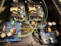

I'm guessing that by "left" you mean the one that's to the left in the pictures. That channel has its input much closer to the SMPS than the right channel so I would expect it to be the noisier of the two.
Would you mind quantifying "quieter"? Did you measure or is it a subjective experience kinda thing?
Also: Why was C27 omitted?
Tom
Would you mind quantifying "quieter"? Did you measure or is it a subjective experience kinda thing?
Also: Why was C27 omitted?
Tom
Yes to the left in the photo. Quiet as in audibly/subjectively much quieter. No hum or noise, just quieter.
Thanks for catching C27. I missed it being in its own row on the BoM.
Thanks for catching C27. I missed it being in its own row on the BoM.
So if quieter doesn't mean lower noise/hum, what does it mean? Does it seem like it has lower gain? You could measure that... I go through how to do that here:
If you're using RCA inputs you need to make sure that both pins 1 and 3 on the input of the Modulus-86 are connected to the RCA shell. The centre pin of the RCA should connect to pin 2 of the MOD86 input.
Tom
If you're using RCA inputs you need to make sure that both pins 1 and 3 on the input of the Modulus-86 are connected to the RCA shell. The centre pin of the RCA should connect to pin 2 of the MOD86 input.
Tom
Yes, it's as if the left channel has much lower gain. The RCA shield and ground are intertwined and soldered at the RCA inputs as instructed (I removed and replaced wiring twice to be sure that was not the cause). All inputs isolated from chassis but I'll triple check. I'll take a look at the video. Thanks.
Results with 1.016v 400Hz sine output from gieson.com via PC line out:
Left channel: 5.57v
Right channel: 10.14v
Left channel: 5.57v
Right channel: 10.14v
Well, that's intriguing. Thanks for taking the measurements. Now we have data to work with.
If you're confident that the input and output wiring is good, you're dealing with a case of wrong component installed. Most likely you accidentally swapped two resistors. 2 kΩ and 20 kΩ are easy to swap, for example. I'd look around R4, R7, R17, R18 in particular. Compare the coloured bands on the resistors between the left and right channels. I bet you'll find some of them out of place.
If you post a high-resolution picture of the left channel board taken from the top with good lighting I can help you find the offending part.
Tom
I did have some resistor confusion during the build (I have a hard time with color bands and contemplated using different type with numeric designation but wanted this build to be 'by the book') - so this is a likely culprit. Will look over and report back. Thanks.
I seem to have trouble discerning brown, red, orange even with 90+ CRI LED lighting. I'm not sure if the manufacturers are getting sloppy with the paints, my eyesight is failing, or the lighting is worse than the incandescent lights of years past. It may be any combination of the above.
Tom
Tom

I've noticed that small TH resistors have a sometimes ambiguous color scheme, browns and reds are usually the worst, grey and white or grey and blue can get tricky, so I keep the meter handy just in case.I seem to have trouble discerning brown, red, orange even with 90+ CRI LED lighting.
It makes me wonder if the manufacturers are cheapening out on the paints. I have no issues reading the colours on older resistors. I have some carbon film ones that are probably 20-30 years old and their colours are clear as day.
Tom
Tom
Tom,
For the Mod 86 2.4 BOM
Would this 667-ECE-A0GKS221 work in place of the 647-UMW0G221MDD?
Would this 667-ECE-A1HKA220I work in place of the 647-UPM1H220MED1TD?
For the Mod 86 2.4 BOM
Would this 667-ECE-A0GKS221 work in place of the 647-UMW0G221MDD?
Would this 667-ECE-A1HKA220I work in place of the 647-UPM1H220MED1TD?
The electrolytic capacitors in Rev. 2.4 are not critical. I usually search for: Same pin spacing. Same or smaller diameter. Same capacitance. Same or higher voltage rating as the ones specified. Buy a name brand. I usually go for Nichicon, Panasonic, KEMET, or CDE. I also tend to choose long-life types.
For the LM317 and LM337: It needs to be the 'L' version. So LM317L and LM337L in TO-92 package. The manufacturer doesn't matter.
Tom
For the LM317 and LM337: It needs to be the 'L' version. So LM317L and LM337L in TO-92 package. The manufacturer doesn't matter.
Tom
Well, that's intriguing. Thanks for taking the measurements. Now we have data to work with.
If you're confident that the input and output wiring is good, you're dealing with a case of wrong component installed. Most likely you accidentally swapped two resistors. 2 kΩ and 20 kΩ are easy to swap, for example. I'd look around R4, R7, R17, R18 in particular. Compare the coloured bands on the resistors between the left and right channels. I bet you'll find some of them out of place.
If you post a high-resolution picture of the left channel board taken from the top with good lighting I can help you find the offending part.
Tom
Well the troubles continue. The resistor R7 was indeed the culprit I think - it was 2k instead of 20k. I say I think because no sooner did I replace it with the correct value and turn on the amp to verify... black smoke rose from the right channel. Using the multimeter somehow the LM3886 on the right coupled with the chassis? No idea how as it's been solidly isolated the whole time (some days now) and I repeatedly check to make sure.
This build just doesn't seem like it's meant to be. Quite frustrating.
- Home
- Amplifiers
- Chip Amps
- Modulus-86 build thread