I'm thinking that's 1.1% flux content. If you have the part number you could always have a look-see on Kester's website.
Tom
Tom
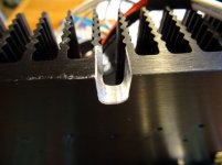
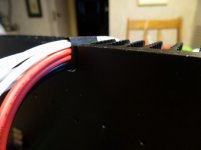
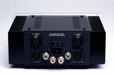
So I'm finally building my Parallel86. I milled a channel in the top edge of the heatsink for running wires from the Antek to the AC power module. While doing that I made it a bit wider and deeper thinking it would also be a good place to run wires from the power86 to the parallel86 boards. I rounded all edges of the channel but thought it would be good to run the wires in heat shrink tubing as extra protection. Turns out all four AC leads and six power86 leads fit in one piece of heastshrink tube. Is there any issue running all the wires togehter?
Attachments

Did that and /245 indicates it is flux cored.I'm thinking that's 1.1% flux content. If you have the part number you could always have a look-see on Kester's website.
Tom

I'm not seeing any issues from a performance point of view. From a safety point of view I'd be a bit concerned about the wires chafing.
Tom
Tom
All edges of the channel were filed and sanded very smooth and the heatshrink tube is very thick with internal adhesive. I don't think there will be any chafing. Over the last six years It has always been a pleasure and learning experience talking with you. As always I thank you for your help.
I'm ready to put the silpads on the lm4780s. Since the pads are blue on one side and white on the other I thought it might be color coding. I doubt it matters but color coding seems common on many electrical components. Does it matter what side goes on the lm4780?
I seem to recall that the blue is a foil that you need to remove before the final assembly. The pads are not directional.
Tom
Tom
Blue is the color of the silpad. A clear protective film is peeled off and the pad, which is lightly tacky, can be be put on the lm4780. The white side is a white plastic film that can be rubbed to get the pad seated on the lm4780 and then it is peeled off. Now the lm4780 can be secured to the heat sink.
The Parellel86 is wired except for the speaker binding posts. I thought I would check the connections with my digital multi meter. The results are confusing. As expected, with one probe on the power86 left channel + output and the other probe on the left channel board + input I get continuity. With the probe still on the power86 left channel + output should any of of the other left or right channel board power inputs have continuity?
I think my post was not clear. This is what's happening. With a probe on the power86 left channel + output and the other probe on the pcb left channel + input the meter beeps. When I move the pcb probe to the right channel + power input it beeps The same happens when checking the power86 - output. Thats what is confusing me.
I'm not clear on why you'd find those measurements necessary or insightful. You'll get all sorts of odd results when you measure two random nodes with an ohmmeter or continuity tester.
I recommend that you test the power supply before connecting it to the rest of the circuit. If the supply checks out OK, turn the power off and wait for the supply capacitors to discharge. Then connect the power supply to the amp modules. You can see that at the 1h02m mark in this video:
If you have the inputs, outputs, and power supply connected as shown in the design doc, the amp will power up just fine.
Tom
I just took the cover off my modulus86, which works perfectly, and got the same results. Everything is OK.
Hello all, Just wondering if Modushop Dissapante U2 heatsink x 230mm is enough for a 286 mono into 8ohms using a Connex SMPS 300RE 30V as power? Only moderate DBs..??
Thanks
Thanks

Thanks Tom,
I was actually thinking of using two of the small galaxy Aluminum chassis as Mono amps. Each with one side swapped with a U2 40mm Heatsink. I will also be building a stereo using a larger/longer mini dissipante. Nice to know this is possible.
I was actually thinking of using two of the small galaxy Aluminum chassis as Mono amps. Each with one side swapped with a U2 40mm Heatsink. I will also be building a stereo using a larger/longer mini dissipante. Nice to know this is possible.
Just to be clear, 40 mm is the fin depth not the height, right. We're talking about using the 2U tall x 40 mm deep x 200-300 mm wide heat sinks.
The Galaxy chassis rely on threads in the side extrusions for the bolts that hold the chassis together. You can certainly buy a Galaxy chassis and some heat sinks and make a chassis out of that, but it'll require some work to get everything working together. I think you may be better off just buying the heat sinks (ModuShop sells them in the Spare Parts -> Dissipante section) and some sheet aluminum.
If you're thinking to cook your own chassis from ModuShop parts, I recommend that you contact them for the CAD drawings. That'll make it easier to see if the parts can be made to fit together.
Another option could be to put the heat sink on the rear panel - or inside the chassis aligned with the vent slots.
Tom
Correct, 40mm fin depth. U2 ~80mm tall. 😎
Thanks, I know I might have to modify the HeatSinks and Chassis to get this to all work well. I will post some photos...
Thanks, I know I might have to modify the HeatSinks and Chassis to get this to all work well. I will post some photos...
That'd be cool. I wonder if you can make some internal brackets from aluminum angle extrusion. That would allow you to have the top/bottom of the chassis be flush with the top of the heat sink. Or ... if you have access to a milling machine, remove the top, bottom 2-3 mm of the heat sink base to allow the top/bottom panels to sit flush. That'd look pretty classy.
Tom
Tom
- Home
- Amplifiers
- Chip Amps
- Modulus-86 build thread