Nice build! Tom’s stuff is pretty special. I have a Mod-286 he built and his TCA HPA-1 headphone amp, and I gifted my son his TCA HPA-10 headphone amp. We’re very happy with all three pieces!Another successful build...
Wanted to build an amplifier for quite a while and get back into soldering so I started with the LM3886DR from Neurochrome which was fun and super easy. But I wanted more and decided to also build the Modulus86 which was even more fun. Only sourcing parts is not trivial in these time, but Tom helped to find alternatives.
Sound is so clean and amazing and I never thought that my old speakers could play so well. Will still get new ones soon. Case is from Hifi2000 and the DAC I use is an EVO-Sabre from audiophonics plus Kali which will go in a similar clean case together with a Sigma11 linear power supply.
That's a nice and tight build. Congratulations on a build well done. I'm glad to hear that you like the results.Another successful build...
Tom
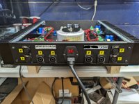
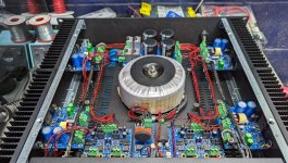
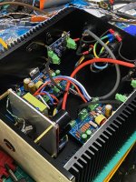
I have just completed a build for a 4 channel Modulus-86 build. I was in the market for a DIY amp for 4 horn subs that I was building, and needed around 50 watts into 4 ohms, the modulus-86 was perfect for my application, gain was spot on and so was output power at ultra low distortion levels. I already had the antek transformer too, which happened to be the correct voltage for the build. I used a Dissipante 2U chassis for the build with steel covers as it will be rackmounted.
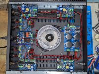
Since the hornsub drivers are non replaceable in the boxes I built, I needed as much protection as possible, so I also used the Guardian 686 boards in this build for the 4 channels. For power I used Tom's ISS and Power-686 boards.
Tom's boards, build documentation, and engineering are hands down the best of any DIY build I've completed so far, the assembly process was non trivial as the most complicated part of the build was sourcing the LM3886 due to shortages, but I was able to secure enough and some extras for the future. Chassis metal work and wiring by far took the longest. I had all boards soldered and ready in a day, but it took a good week off and on to complete the rest.
All 4 boards measured perfectly to Tom's spec, with ultra low DC offset's in the uV range on all 4 boards. The noise floor is lower then my measuring equipment, and compared to my last build of Orchard audio amps, lower as well. Overall I am extremely satisfied from start to finish in dealing with Tom and his products, not very often you have a solidly engineered product, sold for the DIY community!
I have yet to listen to the amp, as I am just finishing off the subs, and room, but I am sure it will perform fantastic!
Thanks again Tom for your designs, and excellent documentation and engineering knowledge that you have shared with the community.
Attachments
Nice build! Tom’s designs are top notch.I have just completed a build for a 4 channel Modulus-86 build. I was in the market for a DIY amp for 4 horn subs that I was building, and needed around 50 watts into 4 ohms, the modulus-86 was perfect for my application, gain was spot on and so was output power at ultra low distortion levels. I already had the antek transformer too, which happened to be the correct voltage for the build. I used a Dissipante 2U chassis for the build with steel covers as it will be rackmounted.
Since the hornsub drivers are non replaceable in the boxes I built, I needed as much protection as possible, so I also used the Guardian 686 boards in this build for the 4 channels. For power I used Tom's ISS and Power-686 boards.
Tom's boards, build documentation, and engineering are hands down the best of any DIY build I've completed so far, the assembly process was non trivial as the most complicated part of the build was sourcing the LM3886 due to shortages, but I was able to secure enough and some extras for the future. Chassis metal work and wiring by far took the longest. I had all boards soldered and ready in a day, but it took a good week off and on to complete the rest.
All 4 boards measured perfectly to Tom's spec, with ultra low DC offset's in the uV range on all 4 boards. The noise floor is lower then my measuring equipment, and compared to my last build of Orchard audio amps, lower as well. Overall I am extremely satisfied from start to finish in dealing with Tom and his products, not very often you have a solidly engineered product, sold for the DIY community!
I have yet to listen to the amp, as I am just finishing off the subs, and room, but I am sure it will perform fantastic!
Thanks again Tom for your designs, and excellent documentation and engineering knowledge that you have shared with the community.
That is a very nice and tidy build there. I'm glad to see that it came together nicely for you. Good to hear that it measured to spec in your hands as well.
Tom
Tom
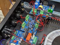
I hope that bolt to attach the transformer isnt as tall as it looks in the picture and doesnt touch top cover
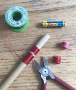
I've found it's less awkward...
to wind magnet wire for the Thiele network inductors using about 8 inches of 1/2-inch diameter wooden dowel as a former instead of an AA battery (shown for size comparison). It's especially handy if you're going to need more than two inductors. Wind one long length of coil for as many inductors as you'll need, plus a bit extra for safety, then snip each inductor's worth from the coil.
to wind magnet wire for the Thiele network inductors using about 8 inches of 1/2-inch diameter wooden dowel as a former instead of an AA battery (shown for size comparison). It's especially handy if you're going to need more than two inductors. Wind one long length of coil for as many inductors as you'll need, plus a bit extra for safety, then snip each inductor's worth from the coil.
Attachments
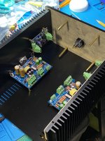
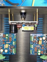
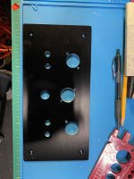
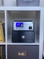
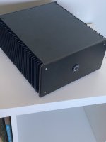
Completed a modulus-86 v3 build using a smaller form factor chassis I picked up from AliExpress. Went with the connex SMPS module and Guardian-86 speaker protection. I vertically mounted the SMPS module and it worked out quite well with this chassis. Went with the Dale Vishay and Burson opamps as per @mkrawcz’s post. Super happy with how the build turned out. The chassis is compact and fits nicely inside the Ikea Kallax. A popular YouTube reviewer calls these compact hifi equipment Kallax-Fi 🙂 Tom's PCBs are of top notch quality. Luckily, I did not have to bug Tom as the build went relatively smoothly and I was able to resolve whatever snafus I encountered along the way (mostly my own gaffes).
Attachments
-
 E3643B37-6F16-46C2-9894-D4EC62E9A5B3.jpeg428.2 KB · Views: 350
 -
 8B055807-9F71-4168-9B67-9F1E13BC0F9F.jpeg537.1 KB · Views: 351
 -
 25C72179-CF79-4852-BE3C-749F5CD366A6.jpeg479.5 KB · Views: 338
 -
 87AA68F3-5557-41B4-B40C-0EB8BFB644ED.jpeg600.6 KB · Views: 336
 -
 43E02DE0-4230-452F-8292-370BAAA9A4BC.jpeg404.2 KB · Views: 346
 -
 C0A95118-C96F-4C96-BDE1-607E09768562.jpeg446.9 KB · Views: 311
 -
 70748FF6-162A-4D10-92D4-2310E9C6B284.jpeg228.1 KB · Views: 338
 -
 EAA60320-63AD-4903-AE31-9946E63B5D8E.jpeg256.2 KB · Views: 330
 -
 2B498EC3-2B38-4CCC-99E8-E82DF94CF1ED.jpeg399.2 KB · Views: 351
 -
 IMG_7973.jpeg542.1 KB · Views: 391
Last edited:
Kallax-Fi... LOL <snort> 🙂 What are the dimensions of the Kallax shelves? 30x30 cm?
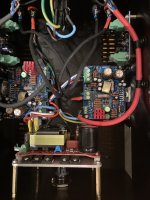
Interesting idea with the power supply mounted with standoffs to the front panel. As long as you're a bit careful with the mains routing that should work quite well. Keep the mains wiring away from input cables. The way I often do that is to zip tie the input cabling to the spare holes in the heat sink brackets.
Thanks for sharing.
Tom
33x33cm to be precise.Kallax-Fi... LOL <snort> 🙂 What are the dimensions of the Kallax shelves? 30x30 cm?
Interesting idea with the power supply mounted with standoffs to the front panel. As long as you're a bit careful with the mains routing that should work quite well. Keep the mains wiring away from input cables. The way I often do that is to zip tie the input cabling to the spare holes in the heat sink brackets.
Thanks for sharing.
Tom
The SMPS assembly along with the anti-vandal switch behind the SMPS was the trickiest part. Yes, I did route the input cables along the heat sinks in the final assembly. The modulus-86 is making sweet music. Life is good! 😎
Keep the mains wiring away from input cables.
Good idea. In general I think that's a bad orientation for the power supply because it maximizes the radiated EMI throughout the chassis. The rectifier and transformer being in such close proximity to the sensitive analog inputs will cause noise. I would at least put an aluminium can around the supply, or a grounded "wall" to separate the supply section and absorb the EMI/RFI emissions from that switch mode supply.
Radiated noise from an SMPS is not that big of a deal. A few years ago I offered an ultra compact Modulus-286 Kit powered by a Connex SMPS300RE mounted on a mezzanine plate right above the amp modules. The distance from the power supply to the amp modules was maybe 25-30 mm.
You can see the resulting performance in Amir/ASR's review: https://www.audiosciencereview.com/...urements-of-neurochrome-modulus-286-amp.6443/
The difference between channels is due to the proximity of the rectifier in the SMPS to the input section of one channel. Most builds will look much like the 'blue' channel in Amir's plots as few pack things as tightly as I did in the MOD286 Kit.
Some of you may notice that Amir measured 95 W whereas I specify 125 W into 4 Ω from the Modulus-286. The difference is caused by the power supply. The SMPS300RE is a bit under-powered for an amp that's to deliver a sine wave at clipping levels into a 4 Ω load. It'll deliver 125 W with one channel driven and 2x95 W with both channels driven.
Music signals demand much less of the power supply, which is why I still recommend that power supply for those who wish to amplify music.
Tom


I've seen that review Amir did some years ago. It's worth pointing out that the supply in your case was sitting on a metal plate:

which acted more or less as a shield, especially if it was grounded. Additionally the ground plane on the bottom side of the PCB further helped to absorb EMI. I am willing to bet that if you remove the plate and turn the supply around so it's facing the amps, you will get a lot of wideband noise.
which acted more or less as a shield, especially if it was grounded. Additionally the ground plane on the bottom side of the PCB further helped to absorb EMI. I am willing to bet that if you remove the plate and turn the supply around so it's facing the amps, you will get a lot of wideband noise.
I think you may be assuming that the coupling between the SMPS and the amps is capacitive. A shield could help minimize capacitive coupling as it provides a termination point for the electromagnetic field lines. But in order for a shield to work well it has to be solid. The mounting plate has several holes in it for wire grommets. It's only barely wider than the SMPS so it wouldn't have much impact on the fringe capacitance either. So I doubt the plate would do much for shielding - even if the coupling was capacitive.
I'm willing to bet that the coupling inductive. At least I find it very hard to believe that there's sufficient parasitic coupling capacitance between the SMPS and the audio circuit to cause capacitive coupling at 60-120 Hz. Shielding doesn't do much against inductive coupling. Sure. With a thick enough plate you can get some attenuation. But a 1.6 mm aluminum sheet won't give you much attenuation. A dB maybe... One could go and calculate that...
In the original design of the mezzanine plate I had the power supply rotated 90º clockwise compared to the final design. That made for easier wire routing but it also put the mains input, rectifier, and mains filter right above the input section of the right channel, which resulted in a significant degradation of the THD+N due to the induced mains hum.
Tom
Would not a steel plate be better for inductive shielding? IMO aluminum or mu-metal would largely be ineffective in protecting against AC hum inductively coupling into signal portions of a preamp.
Mu-metal would work. Steel is less effective, but better than aluminum. I seem to recall that 1 mm of steel has the same attenuation as ~5 mm of aluminum (numbers free from memory, usual disclaimers apply).
You can look up (or calculate) the skin depth for various materials at 50/60 Hz and compare. The skin depth is the thickness of material required to reduce the current density to 1/e of the value at the surface (e being the base of the natural logarithm or roughly 2.7).
A mu-metal can would certainly work to contain the EMI from the SMPS. But it'd have to be a can in order to shield the supply effectively. A sheet would probably help a little, but if you really want to push the EMI down you do need to attenuate all the EM field lines.
Tom
Yes, a mu-metal can is necessary; a plate would be a waste of money. But the cost of a mu-metal can would be substantial, and one needs to be careful about (physically) working it otherwise its shielding properties would be destroyed. Steel plate would be effective for inductive coupling, but not really effective for RFI - again, an enclosure is needed. Since the primary concern here is EM at 50/60 HZ it seems that steel shield plate is most cost-effective and practical approach.
I agree that a plate would be the most cost-effective and practical approach. It just wouldn't do much against the EMI as nothing prevents the field lines from wrapping around the plate.
I also agree with your comments about machining mu-metal. You do have to be careful with it or it'll lose its shielding properties.
A plate that covers the full width and length of the chassis and connects to the heat sinks and front/rear panels could be effective as that would make the top half of the chassis a separate Faraday cage from the lower half (assuming you could get the wires through without making holes in the plate, that is). That's similar to the approach taken by Benchmark in their AHB-2 power amp. I could certainly have done that for the MOD286 Kit but it would have made the plate much more expensive (it'd need some joggle bends to get around the amp modules) and it would make the Kit all but impossible to assemble. As it was I already had to get Cristi/Connex to use capacitors with a lower height than their standard caps to make the supply fit in the chassis. Too many sardines. Not enough can... 🙂
Tom
- Home
- Amplifiers
- Chip Amps
- Modulus-86 build thread