How much were looking for? I have a friend that could use it but no promises. Just had his first child so wife is spending a lot elsewhere.... 😱
We should continue this in my for sale thread
FOR SALE: Neurochome MODULUS-686 Stereo Amplifier over 200 watts per channel
These wives !How much were looking for? I have a friend that could use it but no promises. Just had his first child so wife is spending a lot elsewhere.... 😱
"Modulus-686 is currently sold out and on hiatus", so whoever wants to buy should buy it fast.
Last edited:
Yeah. I'm revisiting a few things in the circuit. I doubt I can move the performance much, but I would like to make assembly easier and reduce cost on the (silly expensive) mechanical parts.
I expect to have the MOD686 back by Christmas or early next year. Of course, this does assume I can get the parts on time. The lead times get longer and longer these days.
Tom
I expect to have the MOD686 back by Christmas or early next year. Of course, this does assume I can get the parts on time. The lead times get longer and longer these days.
Tom
Testing procedure
I've built all 4 amps now, and am getting ready to finish everything off, but have a quick question on testing. I did the first test, using 24V on Power+ and 0 on Power-, and everything dropped to 0mV after a few seconds.
Then applied the sine wave to the inputs, but got 0mV output on all 4 amps. I didn't have the final set of IC's inserted - should I? Will test again when I'm more caffeinated.
I also have a new laser cut base, and also did the back panel this time. It's all coming together nicely. Slotted the mounting holes for amps, so the LM-3886's are flat on the heatsinks.
Yep. If you also have 0 V DC on the output of the MOD86 amps, proceed with the following:
If this checks out, the amp is ready for use.
- Create a 5-second long 400 Hz test tone at -3 dBFS using wavtones.com.
- Connect your audio player to the amp and play the test tone on repeat.
- Turn up the volume until you get a good strong signal (say 100 mV RMS AC) on the input of the MOD86 (measure from pin 2 to pin 3 of the input connector).
- Measure the output voltage with your AC voltmeter. You should have Vout = 10*Vin, so 1.0 V RMS AC for 100 mV in.
Tom
I've built all 4 amps now, and am getting ready to finish everything off, but have a quick question on testing. I did the first test, using 24V on Power+ and 0 on Power-, and everything dropped to 0mV after a few seconds.
Then applied the sine wave to the inputs, but got 0mV output on all 4 amps. I didn't have the final set of IC's inserted - should I? Will test again when I'm more caffeinated.
I also have a new laser cut base, and also did the back panel this time. It's all coming together nicely. Slotted the mounting holes for amps, so the LM-3886's are flat on the heatsinks.
Attachments

I didn't have the final set of IC's inserted - should I?
Yeah... The amp won't work unless all the components are mounted.
Tom
Three random and unconnected things in order of immediate usefulness:
1. In the Mod86 description you talk about adjusting gain via the feedback resistors but the Parallel 86 documentation suggests that isn't done. Recently changed pre for a build with quite a bit less gain, so is it really not a good idea to change out the 1K resistors at the the start of the loopfor say 510R.other than the normal reduction in measured performance?
2. I am pondering swapping out the standard gainclone stages in my mancave system for Mod 86 boards (it has been getting a lot more use recently for some reason...) but that currently uses 24dB/octave LR active crossovers with unbalanced output. Could the output from them (currently running through a coupling cap) go to the board after the THAT chip in a sensible way?
3 and very much requiring a considerable surplus of round tuits before it happens: have you ever looked at the output noise levels at the switching frequency of SMPSs to compare to linear supplies?
Yeah... The amp won't work unless all the components are mounted.
That would explain it. All 4 modules worked.
Thanks (again) Tom
That would explain it. All 4 modules worked.
Sweet!
1. In the Mod86 description you talk about adjusting gain via the feedback resistors but the Parallel 86 documentation suggests that isn't done.
Messing with the gain impacts stability. The Modulus-86 Rev. 2.4 is newer than the Parallel-86, so its documentation contains lessons learned in the meantime.
Reducing the gain below 10x (20 dB) is not possible without swapping out the THAT chip, which basically adds attenuation up front. Go with the THAT1206 if you want to go that route.
Increasing the gain to 26 dB is possible by changing a 2k21 resistor to 1k05. I give values up to 32 dB in the design doc (page 14).
2. I am pondering swapping out the standard gainclone stages in my mancave system for Mod 86 boards (it has been getting a lot more use recently for some reason...) but that currently uses 24dB/octave LR active crossovers with unbalanced output. Could the output from them (currently running through a coupling cap) go to the board after the THAT chip in a sensible way?
Sure. Pluck the THAT chip. Connect pin 3 to pin 6 on the (now empty) THAT socket. Add 47 kΩ from pin 1 to pin 2 on the input connector. Connect the single-ended input from pin 1 (ground) to pin 2 (signal).
3 and very much requiring a considerable surplus of round tuits before it happens: have you ever looked at the output noise levels at the switching frequency of SMPSs to compare to linear supplies?
I don't think I have. I measure THD+N vs frequency with 60 kHz bandwidth and have not noticed any difference between the SMPSes that I have tried and a linear supply. If the difference doesn't show up within 60 kHz bandwidth and isn't causing interference with AM radio or whatnot, I don't think it's worth worrying about.
I do have a few instruments that'll measure above the audio band (in a few cases well above the audio band) but they don't have fantastic dynamic range. Most RF gear seem to have ~80 dB dynamic range. I'm sure there are exceptions, but I don't have $50k floating around to buy a new spectrum analyzer. If I did have $50k floating around, I'd spend $32k of it on an APx555. 🙂
Tom
Hi Tom,
Do the changes to the 2K21 to change gain also apply to Rev 2.0 which I have?
How's the hockey?
cheers
t
Do the changes to the 2K21 to change gain also apply to Rev 2.0 which I have?
How's the hockey?
cheers
t
I'm building a 6-channel amp based on Modulus-86 amps. This is my first amp build, but I do have experience with electronics in general, including construction of modular analog synths from bare PCBs until the final product. So I just need a little bit of hand-holding for this amp because the world of home audio and some of the technical bits are just unknown to me and I have no idea what to search for on Google. I have gone through and read lots and lots of previous threads, but I still have questions because everyone's amp builds are all so different.
I put together a PDF diagram showing the basic layout of my system. It should be attached to this message -- it's only 86k so take a look before reading the remainder of this post. It's a functional diagram only, to make sure I'm accounting for all of the internal connections and connector parts. I do not show the entirety of the wiring between the Power-86 and Modulus-86 boards because this is basically "plug and play" and Tom's instructions are very clear.
I need help with three main parts of the build:
1) I'm looking at a Dissipante 3U with external dimensions of 440W x 313D x 126H. Is this a good choice? My amp shelf has 400mm from the front edge to the wall behind it, about 450mm of possible width, and 170mm of height available. This should give me plenty of space behind it for XLR connections and such. Based on some quick calculations of the sizes of the 9 PCBs and the trafo, it should all squeeze in there.
Disspante 3U 300mm / 10mm front / 3mm aluminum panels
1A) For chassis holes, I've got 6 XLR connectors, 12 speaker terminals, and 1 switched IEC connector on the rear, and 6 LEDs on the front. Is that it? I need to be certain before I order the chassis because I'll have it drilled by the Dissipante folks.
1B) How are all of the various PCBs and such mounted to the inside of the chassis? The Dissipante product page doesn't show any internal pics so I'm kinda confused. Is it just a flat metal bottom that I'd have to drill holes into? If so, what are the recommended tricks to mounting PCBs and other parts to it?
---
2) Help educate me on some of the more important aspects of the internal wiring. Right now I'm stuck on a few things:
2A) Grounding. It's about 50/50 whether or not an apartment here in Japan will have grounded outlets. I need to do the wiring to account for plugging it into grounded or un-grounded outlets. Is there anything special about it? I guess I'm still a tiny bit mystified by the internal chassis grounding too... if someone could show some clear pics of how this is ideally done in a chassis that has multiple power distribution boards that'd really help. It's my basic understanding that all the grounding should go to a common point on the chassis via individual wires, and not be daisy chained, and not depend solely on the chassis itself as the only ground path. Is that about right?
2B) How to split the output of the transformer to 3 of the Power-86 boards. Is there some common terminal block that's used for DIY amps to make this easy for 4-in / 12-out? Can anyone link me to a specific product? I can't find anything on Google.
2C) What wiring should go from the XLR inputs to the Modulus-86 boards? Would something like Canare L-4E6S 2-core shielded cable be okay? What about the wire from the Modulus-86 outputs to the speaker terminals?
2D) The IEC Connector has a switch on it, but is there any advantage to also including a switch (which I'd put on the front panel of the enclosure) between the output of the transformer and the inputs of the Power-86 boards and flip that one on a couple seconds after the transformer? Basically a switch immediately before the power distribution block.
Any other tips are appreciated, especially if it's along the lines of "things you wish you knew when you built your first amp" etc. Recommendations for which brand of "banana" speaker terminals to use? Types of internal connectors and other wiring tricks that make everything nice and clean?
Thanks a lot!
Attachments
Last edited:
Do you have all the Neurochrome boards yet? I would use a power-686 instead of the 3 power-86 especially since you only have one transformer. I only have 2-way speakers so I am using speakons on my 4 channel Mod-86 amp. Simplifies the connections and wiring. Mogami and Belden make XLR cable which is a 2 conductor with shield. To mount the boards you have to drill some holes in the bottom cover or get the baseplate that Modushop sells to mount the boards to.
I'll start with the question in your .pdf file:
I generally recommend 16 AWG stranded wire internally in the chassis. If you'd like to use fancier speaker cable, go ahead, but it's really not necessary. If I was completing the build, I would probably use some 14 AWG generic speaker cable that I just happen to have a spool of.
You mention you're in Japan where no protective earth is provided by the mains outlet. I would still take the earth terminal of the IEC inlet to the chassis. The terminal is there, you might as well connect it. Your mains cable will, unfortunately, not include this earth terminal. Such is life.
This does mean that you are relying on the insulation in the transformer to protect you from the mains voltage, however. So you do want a Class II transformer (electrical safety Class II that is). With your 100 V nominal mains voltage, a Hammond 1182S24 2x24 VAC (at 117 V mains, so more like ±21 VAC with 100 V mains) 500 VA transformer would be perfect. That should get you pretty darn close to ±30 V rectified under load at the output of the Power-86.
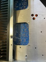
I think that's an excellent choice. The MOD86 boards are 90 mm wide, so you'll have to stagger them on the heat sink. That should be manageable even though it is a bit more involved mechanically. You could also entertain the thought of mounting the boards vertically on the heat sink.
The main challenge there is that you'll need to fashion a bracket of sorts to hold the boards. Personally, I would take a piece of sheet aluminum and bend it in a vice to form a 90º angle bracket. I'd then drill holes in the bracket such that it could mount to the heat sink and hold the board. Someone here fashioned brackets out of a piece of aluminum channel. You should be able to dig out the pictures within the past 20-or-so pages of this thread.
Another thought is that with the 3U tall chassis, you have some room vertically so you could entertain the thought of making a mezzanine (shelf in the middle of the chassis). Just be careful that you don't make a shorted turn around the transformer (see the Power-86 doc for more information on that).
I'm not sure where you'll get the six LEDs from. Each Power-86 has an LED output, so I'm thinking you'll have three LEDs. The MOD86 does not have an LED output. You could connect an LED to the power supply of each MOD86 if you want. You'll need a 5.6 kΩ, 2-3 W series resistor with each LED.
There are basically two approaches: 1) Use the "holey" internal plate provided by ModuShop or 2) drill into the aluminum bottom panel.
I prefer option 2). The holes in the MOD86 and PWR86 were not designed for the internal plate, so you'll be drilling holes into it anyway. That's complicated by the holes already there and the fact that the inner plate is made of steel which is harder to drill into than aluminum. The advantage of the inner plate is that it hides all the mounting screws. But ModuShop uses panhead screws anyway, so that's not much of an advantage for me. It would be nice to hide the head of the transformer mounting bolt, though.
You could use a barrier terminal block (ex. Mouser P/N: 538-38780-0109) or a euro-style terminal block (Mouser P/N: 651-3240172 for example). You'll want to split each wire of the transformer's secondary three ways.
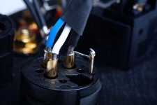
The L-4E6S would be awesome. That's actually fancier than the cable I normally use. There are four wires and a shield in the L-4E6S. You connect the two white wires to XLR pin 2 and the two coloured wires to XLR pin 3. Then connect them the same way at the input to the MOD86. The shield goes from XLR pin 1 to input pin 1. Also ground the XLR pin 1 to the chassis right at the connector. The XLR connector has a tab located by pin 1 for this exact purpose. Just solder a wire to it. See attached image.
A rear panel switch is easy from a mechanical standpoint, but not so great from a usability standpoint. Adding a switch on the transformer secondary side would mean that you drag the noisiest wires all through the chassis. That's not my cup of tea.
If you're going for a fancier front-panel switch, I would suggest using my Intelligent Soft Start (ISS). That circuit is currently undergoing a significant design change. I'll make the board smaller and the circuit will have a richer feature set. It will be available only as a pre-assembled module, hopefully for about the cost of the current ISS board + parts (so $150ish).
I like the ones I sell.... 🙂 Gold Plated Amplifier 5-Way Binding Posts for Speaker Output – Neurochrome
I think you'll find the first couple of links in the Modulus-86 Vendor Thread very useful: Modulus-86: Composite amplifier achieving <0.0004 % THD+N.
Tom
I generally recommend 16 AWG stranded wire internally in the chassis. If you'd like to use fancier speaker cable, go ahead, but it's really not necessary. If I was completing the build, I would probably use some 14 AWG generic speaker cable that I just happen to have a spool of.
You mention you're in Japan where no protective earth is provided by the mains outlet. I would still take the earth terminal of the IEC inlet to the chassis. The terminal is there, you might as well connect it. Your mains cable will, unfortunately, not include this earth terminal. Such is life.
This does mean that you are relying on the insulation in the transformer to protect you from the mains voltage, however. So you do want a Class II transformer (electrical safety Class II that is). With your 100 V nominal mains voltage, a Hammond 1182S24 2x24 VAC (at 117 V mains, so more like ±21 VAC with 100 V mains) 500 VA transformer would be perfect. That should get you pretty darn close to ±30 V rectified under load at the output of the Power-86.
1) I'm looking at a Dissipante 3U with external dimensions of 440W x 313D x 126H. Is this a good choice?
I think that's an excellent choice. The MOD86 boards are 90 mm wide, so you'll have to stagger them on the heat sink. That should be manageable even though it is a bit more involved mechanically. You could also entertain the thought of mounting the boards vertically on the heat sink.
The main challenge there is that you'll need to fashion a bracket of sorts to hold the boards. Personally, I would take a piece of sheet aluminum and bend it in a vice to form a 90º angle bracket. I'd then drill holes in the bracket such that it could mount to the heat sink and hold the board. Someone here fashioned brackets out of a piece of aluminum channel. You should be able to dig out the pictures within the past 20-or-so pages of this thread.
Another thought is that with the 3U tall chassis, you have some room vertically so you could entertain the thought of making a mezzanine (shelf in the middle of the chassis). Just be careful that you don't make a shorted turn around the transformer (see the Power-86 doc for more information on that).
1A) For chassis holes, I've got 6 XLR connectors, 12 speaker terminals, and 1 switched IEC connector on the rear, and 6 LEDs on the front. Is that it?
I'm not sure where you'll get the six LEDs from. Each Power-86 has an LED output, so I'm thinking you'll have three LEDs. The MOD86 does not have an LED output. You could connect an LED to the power supply of each MOD86 if you want. You'll need a 5.6 kΩ, 2-3 W series resistor with each LED.
1B) How are all of the various PCBs and such mounted to the inside of the chassis? The Dissipante product page doesn't show any internal pics so I'm kinda confused. Is it just a flat metal bottom that I'd have to drill holes into?
There are basically two approaches: 1) Use the "holey" internal plate provided by ModuShop or 2) drill into the aluminum bottom panel.
I prefer option 2). The holes in the MOD86 and PWR86 were not designed for the internal plate, so you'll be drilling holes into it anyway. That's complicated by the holes already there and the fact that the inner plate is made of steel which is harder to drill into than aluminum. The advantage of the inner plate is that it hides all the mounting screws. But ModuShop uses panhead screws anyway, so that's not much of an advantage for me. It would be nice to hide the head of the transformer mounting bolt, though.
2B) How to split the output of the transformer to 3 of the Power-86 boards.
You could use a barrier terminal block (ex. Mouser P/N: 538-38780-0109) or a euro-style terminal block (Mouser P/N: 651-3240172 for example). You'll want to split each wire of the transformer's secondary three ways.
2C) What wiring should go from the XLR inputs to the Modulus-86 boards? Would something like Canare L-4E6S 2-core shielded cable be okay?
The L-4E6S would be awesome. That's actually fancier than the cable I normally use. There are four wires and a shield in the L-4E6S. You connect the two white wires to XLR pin 2 and the two coloured wires to XLR pin 3. Then connect them the same way at the input to the MOD86. The shield goes from XLR pin 1 to input pin 1. Also ground the XLR pin 1 to the chassis right at the connector. The XLR connector has a tab located by pin 1 for this exact purpose. Just solder a wire to it. See attached image.
2D) The IEC Connector has a switch on it, but is there any advantage to also including a switch (which I'd put on the front panel of the enclosure) between the output of the transformer and the inputs of the Power-86 boards and flip that one on a couple seconds after the transformer?
A rear panel switch is easy from a mechanical standpoint, but not so great from a usability standpoint. Adding a switch on the transformer secondary side would mean that you drag the noisiest wires all through the chassis. That's not my cup of tea.
If you're going for a fancier front-panel switch, I would suggest using my Intelligent Soft Start (ISS). That circuit is currently undergoing a significant design change. I'll make the board smaller and the circuit will have a richer feature set. It will be available only as a pre-assembled module, hopefully for about the cost of the current ISS board + parts (so $150ish).
Recommendations for which brand of "banana" speaker terminals to use?
I like the ones I sell.... 🙂 Gold Plated Amplifier 5-Way Binding Posts for Speaker Output – Neurochrome
I think you'll find the first couple of links in the Modulus-86 Vendor Thread very useful: Modulus-86: Composite amplifier achieving <0.0004 % THD+N.
Tom
Attachments
Last edited:
Thanks wcwc and Tom for the advice and the corrections. I'm much more confident about how to proceed with this build now -- at least enough to order the Dissipante with the correct holes and an appropriate transformer. The Neurochrome PCBs arrive today, and the Mouser parts on Monday... so depending on how long it takes for the Dissipante to arrive, I could have this built within the next couple weeks.
I think once I get all of the parts on my workbench, it'll be much clearer how it all comes together. I'll report back sometime next week with pics of the actual proposed layout for a final check before I do anything stupidly permanent 😎
I think once I get all of the parts on my workbench, it'll be much clearer how it all comes together. I'll report back sometime next week with pics of the actual proposed layout for a final check before I do anything stupidly permanent 😎
I suggest drawing the internal dimensions of the Dissipante of choice to scale on a sheet of paper. Then move the boards around within that shape until you find a configuration that works. It'll be a bit crowded with the three supply boards.
You can also be all 21st century fancy and do the same in a CAD tool.
Do this before ordering the chassis... They're hard to make larger. 🙂
Tom
You can also be all 21st century fancy and do the same in a CAD tool.
Do this before ordering the chassis... They're hard to make larger. 🙂
Tom
Now that I have the boards in my hands, that's exactly what I'm doing 🙂
BTW, I decided to go with SpeakON connectors which should simplify things a bit. I saw that you recommended them a few pages back. I should be able to use 4 SpeakON connectors instead of 12 bananas, right? Two 4-pole + two 2-pole?
One other concern I have is the 6 inputs from the MiniDSP. With the analog sources (e.g. the Schiit SYS or any other preamp) I can turn down the physical volume knob. But with the Optical in, I'm always a little worried about relying on the internal digital volume of the DSP to not be higher than what I think it is.
However, with 6 inputs to the amp, I don't see a solution since I can't find a 6-gang pot and I'm not familiar with any way to use multiple pots together which results in a uniform output from each one. Is it possible? Am I overlooking some simple solution?
The other thing I thought of is that I could get the Alps RK27114 and assign that one to the 4 channels handling ~80Hz and above, and use an RK27112 for the subs, then take measurements to calibrate the approximate positions of each volume knob to be equal on the front panel of the amp once I tighten the set-screw. That would allow me to control the subwoofer volume independently of everything else -- which might be a nice "compromise" that results in some useful extra functionality?
Anything wrong with this idea?
(Did I mention I tend to go overboard on what should be a simple project? Ha)
Anything wrong with this idea?
(Did I mention I tend to go overboard on what should be a simple project? Ha)
Neutrik also makes an 8 channel Speakon connector.
Since you are running balanced you would need to double the number of contacts on the potentiometer needed to 2 per channel.
Since you are running balanced you would need to double the number of contacts on the potentiometer needed to 2 per channel.
Oh, right... so I'd need like a 12-gang pot, which I'm pretty sure doesn't exist. Hmm. Maybe the better option is to get a different preamp in the future which has either a built-in DAC or an extra analog-in to connect an outboard DAC, and don't use the optical-in on the MiniDSP... I dunno, for some reason I really like the security of having all the signals going through a knob that I can touch and see, prior to the amp. It's really too bad that the MiniDSP don't have a master volume knob on the outside -- I don't trust the remote with no visual feedback.
- Home
- Amplifiers
- Chip Amps
- Modulus-86 build thread