I will give it a shot. Thanks for the guidance. I have to order the resistor with the broken lead, so I might as well order 4 new diodes. One of the LM337s and C25 and C29 are corroded. Probably best to replace those too. Recoating the pins on the LM337 looks tricky.
Attachments
Oof! The more detailed shots you show, the more I cringe. In your shoes, I'd get a new board and build that amp channel from scratch. It's $120ish (USD) per channel for board and components if I recall correctly. That way you get an amplifier channel you can trust.
Then again, you can spend $10 in parts and a few hours and try to get it working again. You might get lucky. I'd replace the LM317, LM337, the four 1N4007, and the four resistors, and the two ceramic caps. Just unsolder that handful of components and throw them out. Clean up the board as I described a post or two back. You'll probably have to tin the through-plating in the holes, i.e. fill the hole with solder and suck it back out with a solder sucker.
Tom
Last edited:
The design doc I got with my order was out of date and says it's R13 which must be changed to 40.2 kilo Ohm for 26db gain. I remember you correcting that for me but I can't find my notes. Just wanted to check it wasn't wasn't R21 or R22.
If you want 26 dB gain, changing R12 to 1.05 kΩ is better than changing R13. That said, R13 = 40.2 kΩ will give you 26 dB gain as well.
R19-22 are all in the power supply.
I don't think I have the docs for Rev. 2.0 anymore, but Rev. 2.1 is very similar. Rev. 2.0 uses the 8-pin DIP version of the LME49710(NA). Rev. 2.1 uses the TO-99 metal can LME49710(HA). If you need an updated copy of the doc, just toss me an email.
Tom
R19-22 are all in the power supply.
I don't think I have the docs for Rev. 2.0 anymore, but Rev. 2.1 is very similar. Rev. 2.0 uses the 8-pin DIP version of the LME49710(NA). Rev. 2.1 uses the TO-99 metal can LME49710(HA). If you need an updated copy of the doc, just toss me an email.
Tom
Last edited:
Snowy, maybe I missed it, but was the amplifier powered up when wet or afterwards? If it was not powered up, your chances are better.
What is picture 2 here?
Sorry: Tom, I refer to your post #3983 and the 3 pictures in the post.
The three pictures in Post #3983 show:
1) One Modulus-86 Rev. 2.3 assembled module
2) Two Modulus-86 Rev. 2.3 assembled modules
3) One unpopulated Modulus-86 Rev. 2.3 circuit board.
Tom
1) One Modulus-86 Rev. 2.3 assembled module
2) Two Modulus-86 Rev. 2.3 assembled modules
3) One unpopulated Modulus-86 Rev. 2.3 circuit board.
Tom
kberge,
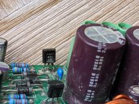
The second picture in post #3983 is an NMOS – STW11NK90Z, used as a cascode device in the 21st Century MAIDA regulator, revision 2.0, which is a redesign of Tom's aimed for tube gear. It is most commonly used for regulating the HV B+ section. Simplistically speaking, the new MAIDA topology is a low voltage regulator with a cascode in front to drop the voltage. The cascode device needs a heatsink and hence Tom's second picture in post 3983 was showing the use of Keratherm Red 86/82 thermal pads as an acceptable and efficient method of heat transfer.
More info available here: 21st Century Maida Regulator, Rev. 2.0. The Keratherm pads are also for sale on his website. It is the lowest thermal resistance pad on the market and fits many devices including LM3886, TO-247, TO-218, and TO-3P.
Best,
Anand.
Last edited:
I bought a whole sheet (A4 size, 21 x 30 cm) of Keratherm on eBay and saved an amazing amount of money compared to individual precut pads from the diyAudio Store or other vendors of convenience.
You can cut the Keratherm sheet with regular scissors, and you can create the mounting holes with standard arts and crafts punches. 1/8" diameter punch fits an M3 bolt perfectly. Here is the one I am using, purchased from Amazon for USD 7.66
Amazon.com: Fiskars 23517097J Circle Hand Punch, 1/8 Inch, Purple
" THAT Driver and THAT Receiver in one board" appeals a lot here,
same here i bought my amps with plans to add that driver at a later stage iv only a single ended output and that driver was ideal for my build.
also hoping it will be a diy option
same here i bought my amps with plans to add that driver at a later stage iv only a single ended output and that driver was ideal for my build.
also hoping it will be a diy option
Your link is to #3943 ... not #3983. Thankx a lot anyway for your answer.
Sorry. I must have lost track of the post number I was looking for as I was wading through pages of DIY Audio thread. Sorry about that. By coincidence #3943 has three pictures as well. Direct links are useful... 🙂
The second picture in post #3983 is an NMOS – STW11NK90Z, used as a cascode device in the 21st Century MAIDA regulator, revision 2.0, which is a redesign of Tom's aimed for tube gear.
That's exactly what that is. Here's Post #3983.
I bought a whole sheet (A4 size, 21 x 30 cm) of Keratherm on eBay and saved an amazing amount of money compared to individual precut pads from the diyAudio Store or other vendors of convenience.
If you saved an "amazing amount of money", I wonder whether you've gotten Keratherm or just pink plastic. Amazon is not a distributor of Kerafol products, so you're dealing with a 3rd party vendor (as you would if shopping with me or the DIY Audio store). The DIY Audio Store and I order the thermal pads in rolls of 1000. I know what those cost and, thereby, know the margin. It's not what I'd consider amazing. It's significantly lower than common retail margins - including online retail margins. Then again, your definition of "amazing" could be different than mine and the cost of a sheet could be considerably lower than that of individual pads (though I doubt that).
Buyer beware.
Sheets are convenient for DIYers, though, as you can just cut whatever shape you need. As you point out, the thermal pad is easy to cut with scissors or a utility knife.
" THAT Driver and THAT Receiver in one board" appeals a lot here,
I'm thinking about it. There'll be some SMD components to solder. At least two SOICs.
Tom
" THAT Driver and THAT Receiver in one board" appeals a lot here,
same here i bought my amps with plans to add that driver at a later stage iv only a single ended output and that driver was ideal for my build.
also hoping it will be a diy option
+1 bazillion!!!
Best,
Anand.
- Home
- Amplifiers
- Chip Amps
- Modulus-86 build thread