I cover that on Page 11 of the design doc. 😉
Yeah... The SMPS-86 is a good candidate for a desktop amp or an amp powering efficient 8 Ω speakers. If you're looking to rock your house off the foundation, you'll find the Power-86 or Power-686 to work better for you.
Tom
I saw the shield note on the design doc but was a bit confused. I guess I assumed no need for 2 shields since I was not using shielded cable but rather twisted pair.
As far as the power supply, I just ordered the Power-86 from your website ... is there a benefit of the Power-686 over the Power-86?
In terms of getting Keratherm Red, I am receiving some samples from MHW Thermal and would be happy to send whatever I don't use in my own build to anybody willing to cover the cost of shipping, which should only be a couple bucks, and am posting this now so that some of you other starving students can get samples of that good thermal transfer.
I saw the shield note on the design doc but was a bit confused. I guess I assumed no need for 2 shields since I was not using shielded cable but rather twisted pair.
Ah! You still need to connect Pin 3 to Pin 1 on the input connector if you use a twisted pair to the RCA socket. Otherwise the THAT1200 doesn't know where ground is.
As far as the power supply, I just ordered the Power-86 from your website ... is there a benefit of the Power-686 over the Power-86?
The Power-686 has twice the reservoir capacitance and individual rectifier diodes. It's intended for higher power applications. Some find the added capacitance adds some 'oomph', but aside from maybe 1-2 additional watt of peak output power, there's really no difference between the two in a stereo Modulus-86 amp. I'd consider using the Power-686 in a stereo Modulus-286 amp and will definitely recommend using the Power-686 with the Modulus-686.
Tom
Happy Canada Day!
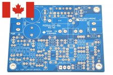
I'm happy to announce that the Modulus-86 is the latest of my circuit boards to be repatriated. Revision 2.4 is made in Canada. The Canadian made boards are also gold plated and fully electrically tested by the manufacturer. High-end manufacturing for a high-end product!
Revision 2.4 includes a couple of layout improvements in the input section. Nothing earth-shaking, but worth taking now that more boards needed to be ordered.
I have parts coming tomorrow to build a stereo pair for testing and expect to have the plots updated on my website later this week. This also means I'll have a stereo pair available for sale soon. Probably in two weeks as I like to sit on the boards for a bit to make sure I got all the measurements.
Tom
Attachments
Great! But that reads 2.40, the nit picky in me wonders what you'll do when you get to the version after 2.9 😀
Oh, I dunno... Do the 'math' thing and invent a new number system. Hopefully, I won't have to resort to the UNIX thing of 2.9.1.3.5.200.g.alpha-stable.... 🙂
I'm running out of tweaks, so unless the ICs get obsoleted by the manufacturers, I doubt it'll ever be an issue. Whenever I've run low on boards, I've often taken some time to revisit the circuit with a fresh pair of eyes. I have yet to come up with something that's better than Rev. 2.3/2.4 or drastically better than Rev. 2.0.
Tom
That still doesn't solve the problem, though. Last I checked 2.11 is between 2.1 and 2.2. So a sequence of ...2.9, 2.10, 2.11 would not make any sense. At least not to those of us who use math on a daily basis.
Maybe by the time I reach 2.9, there'll be enough improvements to justify a jump to 3.0. 🙂
Tom
Maybe by the time I reach 2.9, there'll be enough improvements to justify a jump to 3.0. 🙂
Tom
Picture Day!
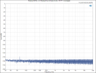
The Modulus-86 Rev. 2.4 performs as well as Rev. 2.3. The THD measures a little higher as I've changed my measurement methodology (fewer points in the FFT to accommodate the slight frequency drift of the oscillator during the measurement). Still at -119 dB vs -125 dB, the difference is academic. Both are orders of magnitude below audible.
One of these days I'll get a Baxendal circuit running so I can measure THD using the AP's oscillator rather than the "Victor's Oscillator" I'm currently using.
The only major difference (improvement!) is in the residual mains hum, which was improved by ~20 dB. Again, mostly of academic interest, but still worth having.
You can find the updated specs here: Modulus-86 R2.4: Composite amp. 70W (4Ω) @ 0.0001% THD
Tom
Attachments
Last edited:
Hey Tom,
I'm very excited about getting my 2.4 boards in the mail and get cracking with the build.
I have a question, it's not something I intend to do but I'm just asking more out of intrigue.
I was chatting with a guy I work with who is also in to DIY audio mainly makes his own phono stages, I showed him this project and he said "You could substitute both the OPA2227 and LME49720 with an OPA627 as they're pin compatible"
He went on to say the OPA627 is the best sounding op-amp.
I expect there may be some audible difference between op-amps when used in something like a phono stage, however I after many years of making music and working with studio equipment I don't really subscribe to subjective audiophile claims, and I also know from reading your documents many times before deciding to build a Modulus86 that you selected each part in this circuit to achieve the best measurements possible.
So just for my own curiosity and to increase my understanding could you answer the following.
1: Why do you use the OPA2227 over the OPA627 (I'm assuming better measurements, or the fact that genuine 627's can cost £30)
2: Can the OPA627 be used in your amp, and if so what would be the impact on measurements or sonic characteristics?
3: Any other relevant information on the subject.
As I said, I have no intention of doing any part swapping, I was drawn to this build because of accuracy/low distortion, and I fully accept that if there was a better part you would have already incorporated it.
thanks
Tom
2:
I was chatting with a guy I work with who is also in to DIY audio mainly makes his own phono stages, I showed him this project and he said "You could substitute both the OPA2227 and LME49720 with an OPA627 as they're pin compatible"
The fact that they're pin compatible does not mean that they are interchangeable. The Modulus-86 depends on the AC characteristics of the LME49720 opamp. If you just plop in another opamp, the amplifier will most likely oscillate.
I did take a look at the OPA627/637 data sheet. The OPA627 could be made to work in the Modulus-86. It would likely require a redesign of the compensation circuits in the Modulus-86 for it to work, and it would definitely require a compensation redesign to get the optimal performance out of it.
The OPA627 is higher noise and higher distortion above 1 kHz than the LME49720, so it is unlikely that it would improve performance.
The OPA627 is more than ten times the cost of the LME49720. In exchange for the >20 dB higher cost and all the work required getting it to work well in the Modulus-86, you get an amp that will likely provide worse performance. Best case, you get a much more expensive amp that provides the same performance. That's not my idea of a good time.
You can certainly use the OPA627 in the DC servo. Keep in mind that a DC servo is a lowpass filter. The DC servo in the Modulus-86 is a 3rd order filter, thus, has a -60 dB/dec slope past the cutoff frequency. I forget the exact cutoff frequency, but it's around 0.1 Hz if I recall correctly. Thus, the DC servo does not have any meaningful output within the audio band. In fact, I chose the filter architecture to ensure that the DC servo had no impact within the audio band - even as the DC servo opamp runs out of loop gain.
Now the OPA627 is only about six times more expensive than the OPA2277, so it's only a 15 dB cost adder. In exchange for that 15 dB higher cost, you gain exactly nothing. You do get the bragging rights of using one of the most expensive opamps on the market. Maybe that's worth something to you... 🙂
He went on to say the OPA627 is the best sounding op-amp.
In his opinion, which he is entitled to. It seems many have a pet opamp. Which one it is depends a bit on which opamps they grew up with.
I expect there may be some audible difference between op-amps when used in something like a phono stage, however I after many years of making music and working with studio equipment I don't really subscribe to subjective audiophile claims, and I also know from reading your documents many times before deciding to build a Modulus86 that you selected each part in this circuit to achieve the best measurements possible.
As you can tell from my perhaps slightly caustic response above, I don't subscribe to the audiophile claims either. I don't deny the audiophiles' experience, but I can think of quite a few cognitive psychological effects that would result in two identical stimuli being perceived differently. Audiophiles are humans too (whether they like to admit it or not).
I can see the potential for an opamp to make a difference in a phono stage, in part due to their high gain. Also, not all filter circuits are created equal. Some make better use of the loop gain of the opamp than others, and some filter topologies have pretty crappy stop band attenuation as result. That would likely impact the performance of the phono stage. It would also be measurable!
Tom
Last edited:
The topic of power supply snubbers pops up every now and then, including in this therad. Thus, prompted by a recent discussion in the Modulus-686 thread, I decided to take a closer look at the topic. I think many of you would find it informative.
You can find my thoughts on snubbers as part of my Taming the LM3886 article series: Power Supply Design: Rectification & Snubbers.
To nobody's surprise, the addition of snubbers to the power supply makes no difference on the output of the power supply or on the output of the power amp connected to the power supply. Thus, I will continue to view claims of audible superiority of snubbers with the same skepticism as I view claims of audible superiority of speaker cable stands, at least in the cases of solid state audio power amplifiers and their power supplies.
That said, a properly designed snubber does reduce the RF ringing that can occur when the rectifier diodes turn off. Thus, I encourage those who are concerned about RF emissions, EMI, and such to use snubbers. 100 nF + 10 Ω will work well. For those who wish to optimize the snubber further, I give a simple iterative procedure. The method I use accounts for the parasitics in the circuit when operated at the target working voltage, thus arrive at a snubber which is much closer to optimum than you'd find with other methods. This method requires no special tools. An oscilloscope and a simple RC filter is all you need.
Enjoy.
Tom
Tom2: I suggest your friend take another look at the OPA627 vs the LME49720 and OPA2277. The OPA627 is NOT the same pinout as the other two -- it is a single op-amp and the ones TomC uses are duals. That's not to say you couldn't find a way to kludge it onto Tom's PCB but "drop-in" (even physically) it is not. TomC's comments on circuit compatibility should be taken into advice.
I have found that most audible differences can be measured, but the data would not be what Tom uses as standard. Normally, if one is really interested in audio, one would first detect a difference, have a clear note of what spect seems more ideal, then find a way to verify the difference and see if different data processing will show an explanation.
I tried the following in place of LME49720
MUSES01
MUSES02
Sparkos SS3601
Sparkos SS2590
First two are pin compatible. Last two are a single opamps, so they require pin adjustments. They also require external regulators since they are Class A and onboard regs are to weak to power them (they get to hot).
I like MUSES01 over the LME49720.
However eventually I ended up with SS2590 powerd by external +/-24V regs. To my ears I found this setup to be sonically the best. It has been running like that for months already.
Tom2: I suggest your friend take another look at the OPA627 vs the LME49720 and OPA2277. The OPA627 is NOT the same pinout as the other two -- it is a single op-amp and the ones TomC uses are duals. That's not to say you couldn't find a way to kludge it onto Tom's PCB but "drop-in" (even physically) it is not. TomC's comments on circuit compatibility should be taken into advice.
To piggy back on Brian's response, I have seen a tremendous amount of opamp swapping circuits and opamp substitution circuits from the audio industry. This is because it is completely marketable. Think Burson, Nord's input buffers, Sparkos, Mivera, etc...
The same audiophiles that grew up on having an entire warehouse of 6922 varieties at their disposal are doing the same with opamps. And why not? It sells more opamps and more amplifiers as a result.
That doesn't mean that their circuits are optimized for said opamp (or 'pin equivalent' set of a variety of opamps!). And it doesn't mean the entire circuit from end to end is optimized at all. They are all in this 'good enough' category. They are a different flavor from absolute neutrality imho, and that is fine.
But...If you look closely at Tom's designs, they are COMPLETE designs. No tweaking necessary whatsoever. His forte is clearly also in PCB layout. This is lacking in most circuits in the industry and especially evident in the various PCB designs across numerous diyAudio forums as well as those designs that have to be "UMS heatsink compatible." That's a lot of designs on the diyAudio store. Why? Because it has to be 1) Cheap, 2) Easy to build, and 3) be compatible with existing heatsinks or have heatsinks that are predrilled for the board. Believe it or not, THAT compromises the circuit design and PCB layout to the point that it does compromise measurements and most likely the transparency of the circuit as well. But that is most marketable and all the power to them for that since the more diy'ers especially newbies that can join the party, the better.
I love DIY and soldering and building various amp/preamp designs. And I do own several of the aforementioned PCB's with substandard layouts, etc...however, I am very aware of the clear advantages of Tom's complete designs and they are reference standards in my opinion. Honestly, they belong in studios and reference systems. If you want Benchmark AHB2 like performance on a budget price, give Tom's Modulus 186, 286 and particularly 686 a whirl. Just choose the amp power that is compatible with your listening habits, room size and speakers.
Best,
Anand.
I tried the following in place of LME49720
MUSES01
MUSES02
Sparkos SS3601
Sparkos SS2590
First two are pin compatible. Last two are a single opamps, so they require pin adjustments. They also require external regulators since they are Class A and onboard regs are to weak to power them (they get to hot).
I like MUSES01 over the LME49720.
However eventually I ended up with SS2590 powerd by external +/-24V regs. To my ears I found this setup to be sonically the best. It has been running like that for months already.
View attachment 766692
Pity. What a travesty.

Unfortunately, you failed to realize that the input stages of the Modulus 86 already runs in "Class A." And honestly, just move on up to the Modulus 186/286/686 series. But since they are SMD, it doesn't allow for "tweaking." See post 4701 for relevant commentary. I guess this diy audio project is certainly a journey for you and not a destination!
Best,
Anand.
Last edited:
- Home
- Amplifiers
- Chip Amps
- Modulus-86 build thread