Just a quick question if i may; does anyone has the BOM file(s) for the Modulus-86 v2.10 or from (any) previous version?
Please PM or email me if you have.
Thanks in advance.
Harm
You need to contact @tomchr directly for that. If you have purchased a kit, then you would have already received it. Are you looking for a replacement BOM?
Just a quick question if i may; does anyone has the BOM file(s) for the Modulus-86 v2.10 or from (any) previous version?
Please PM or email me if you have.
Thanks in advance.
Harm
The BOM comes with the purchase of a PCB. Please contact Tomchr, who is the designer of the amplifier.
The BOM comes with the purchase of a PCB. Please contact Tomchr, who is the designer of the amplifier.
Just like to know what components are used for this amplifier because i have noting with order-, partnumbers from Digikey, Mouser a.o..
I can't work with that, those companies will not be my first choice and it makes it a lot easier if i knew what components must be ordered to build this amp.
Just like to know what components are used for this amplifier because i have noting with order-, partnumbers from Digikey, Mouser a.o..
I can't work with that, those companies will not be my first choice and it makes it a lot easier if i knew what components must be ordered to build this amp.
The answer is to contact Tom.
Harm: As I told you via PM, the Mouser BOM cost of the Modulus-86 is $46.89 (USD) at today's prices. If all you are really after is an estimate of your build cost, then that should be sufficient for you.
In addition to the parts on the BOM, you will need about 90 cm of AWG18 enamelled transformer wire.
It's been brought to my attention that you have attempted to buy the design documentation from other forum members. That needs to stop. Thankfully, the forum members you have approached have been honest and told you no. I thank them for that.
The full design documentation, including the BOM, is available to those who buy my boards.
Tom
Last edited:
It gave me chills when I found out what Harm's occupation is:
diyAudio - View Profile: Harm2k13
Best,
Anand.
diyAudio - View Profile: Harm2k13
Best,
Anand.
Well finally, some (slow) progress in that I have the stands out and emptied of sand and started the trial fitment. This is going to be a little trickier than I have imagined as the box walls are thicker than I thought and my heatsinks are just slightly the wrong size to replace the back wall as had thought. Also will need to compromise on the placement of the 2 mod86 in each box as my cheapskate second hand headsinks had been used and were milled in the centre for a power device. pressing some copper in would solve that, but aint going to happen. As thermally I have plenty in hand mounting in the top 1/3 of the heatsink should work.
I'll get the camera out tomorrow and take some pictures which should make it all clear.
This all seemed like a good idea at the time...
I'll get the camera out tomorrow and take some pictures which should make it all clear.
This all seemed like a good idea at the time...
"Reverse engineer". No wonder he wants the BOM. That along with the board pictures on my website should be enough to reverse engineer the Modulus-86.
In addition to the performance advantages that can be had with 4-layer boards, it has crossed my mind that 4-layer boards are also much harder to copy. That's a nice advantage from a business point of view.
Tom
This all seemed like a good idea at the time...
Gotta love those projects where your mind gets ahead of your parts collection during quiet times.
If you show what you've got, we can probably brainstorm on how to make the goods work for you. No rush.
Tom
No rush?  😉
😉
Bill is the reason this thread is here and why I built my own! Bill, keep the pics coming we will cheer you to the finish line

Best,
Anand.
😉Bill is the reason this thread is here and why I built my own! Bill, keep the pics coming we will cheer you to the finish line
Best,
Anand.
I have to rush as wife has finally realised a smaller pair of speakers might be a good idea in the living room 🙂 . I have all the bits now, its the fitting it together. Esp as its currently -3C in the shed.
Yeah... The weather decided to make it -20-25ºC outside the week I had set aside for amp building back in December. A space heater came in handy for heating the garage enough that my hands wouldn't freeze to the tools.
Tom
Tom
 FYI - Member Harm2k13 has been banned from the forum, for violating forum rule 15, which clearly states: "Using the private messaging system or email to make unsolicited commercial advances or violate the rules."
 The moderators also want to thank those members who brought the matter to our attention, so it can be addressed in a timely manner.
Thanks to the moderators for their attention and efforts to keep DIY Audio a friendly place.
Tom
Tom
Pics!
Right Finally remembered to extract the camera before the living room was taken out of action for the night (just don't ask) and here is the collection of bits I have to work with. Hey MrT managed with 4x2, gaffer tape and nails and he was blowing sh*t up 🙂
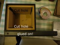
First pic is the speaker stand, with its sand removed. First issue is that the front part is glued on and being over 20 years old the vinyl is it glued to is peeling off. Needs to be screwed on properly. Second is that space is limited so will need to cut a hole front and back. Front so the transformer bolts to the nice thick front piece and back for the transformer.
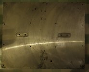
Second pic is my £9 ebay heatsink with bits machined out in just the wrong places 🙂
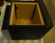
Third pic shows how the heatsink will fit on. It will be screwed to the outside of the box and a hole cut so I can mount the 2 mod 86 on the inside.
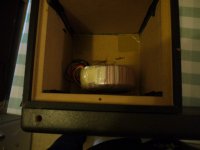
Last two pics are a very rough trial fit to show where things will go. Not got the PSU board out yet, but once the transformer is in its cut out there should just be room. I'll need to drill holes in base and top for air circulation. IO will be on the right hand side (IEC, 5 pin DIN and speakon). Ought to work out where an indicator LED goes as well.
Access will be limited so will make sure leads are long enough to be able to drop the heatsink off to access things.
A tad bonkers, But If I don't c*ck it up will be a nicely packed active setup.
Right Finally remembered to extract the camera before the living room was taken out of action for the night (just don't ask) and here is the collection of bits I have to work with. Hey MrT managed with 4x2, gaffer tape and nails and he was blowing sh*t up 🙂
First pic is the speaker stand, with its sand removed. First issue is that the front part is glued on and being over 20 years old the vinyl is it glued to is peeling off. Needs to be screwed on properly. Second is that space is limited so will need to cut a hole front and back. Front so the transformer bolts to the nice thick front piece and back for the transformer.
Second pic is my £9 ebay heatsink with bits machined out in just the wrong places 🙂
Third pic shows how the heatsink will fit on. It will be screwed to the outside of the box and a hole cut so I can mount the 2 mod 86 on the inside.
Last two pics are a very rough trial fit to show where things will go. Not got the PSU board out yet, but once the transformer is in its cut out there should just be room. I'll need to drill holes in base and top for air circulation. IO will be on the right hand side (IEC, 5 pin DIN and speakon). Ought to work out where an indicator LED goes as well.
Access will be limited so will make sure leads are long enough to be able to drop the heatsink off to access things.
A tad bonkers, But If I don't c*ck it up will be a nicely packed active setup.
Attachments

That will be nice and cosy. And hot! Transformers are not 100% efficient as you know. There is also stuff on the board that will warm the air up. I do hope you and your kids have a good escape plan for when this thing bursts out in flames.
I don't see how it can get hot enough to set MDF on fire once I've drilled the ventilation holes (425F/218C). But thank you for your words of encouragement. I have a 70C thermal cutout as well that will be fitted on the heatsink.
There won't be flames but there will be fumes if the cabinet MDF gets appreciably warm.That will be nice and cosy. And hot! Transformers are not 100% efficient as you know. There is also stuff on the board that will warm the air up. I do hope you and your kids have a good escape plan for when this thing bursts out in flames.
Best to contain those glue fumes by sealing all MDF in a good layer of paint/enamel etc to keep such fumes from releasing into the living room environment.
Dan.
- Home
- Amplifiers
- Chip Amps
- Modulus-86 build thread