I realise the probability of the LM3886 itself failing with a shorted output driver must be very low because otherwise we would have seen accounts of it in these two Modulus-86 threads. However, the consequence of full rail DC through my loudspeaker would be catastrophic. I am risk averse, so would be interested in a protection circuit. On the other hand, I suppose leaving it up to fate would, if the worst happened, be good way to justify a new pair of loudspeakers 🙂
I hear ya. Odds are that I'll offer a protection circuit "one of these days". You could add it later. Speaker protection is like any other risk assessment: [Risk] = [Probability of event occurring] * [Cost of event occurring]. In this case, the risk is very low, but the cost can be quite high.
There are dozens of successful Modulus-86 builds out there. I'm not aware of any failures (knock on wood).
Tom
There are dozens of successful Modulus-86 builds out there. I'm not aware of any failures (knock on wood).
Tom
Last edited:
Tom,
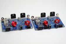
I got modulus 86 build on standard parts with standard gain powered at 28V. Currently connected to 4 ohm speakers. Works nice:
I got two questions:
1. Can I connect it to 16ohm speakers?
2. Can I connect it to 8ohm speakers?
Thanks,
I got modulus 86 build on standard parts with standard gain powered at 28V. Currently connected to 4 ohm speakers. Works nice:
I got two questions:
1. Can I connect it to 16ohm speakers?
2. Can I connect it to 8ohm speakers?
Thanks,
Yes and yes.
Tom
Thanks Tom.
What about the other way: mod-86 @ 35VDC into 4ohm?
My source is 1.4Vrms and it is feeding mod 86 with standard gain.
I am asking because it seems that I will have to power my current 4ohm speakers with mod86@35VDC for a while until I get my new 8 ohm speakers.
What about the other way: mod-86 @ 35VDC into 4ohm?
I suggest reading the power supply section of the design documentation. I've also made numerous posts answering that question in this thread.
LM3886 max output current = 7 A --> 7*4 = 28 V peak in a 4 Ω load. This means you shouldn't use more than Vsupply = ±28 to ±30 V with a 4 Ω load.
If you do run the LM3886 on ±35 V rails, you can expect to get about 50-55 W into 4 Ω before the SPiKe protection engages (as the chip is starting to overheat). With ±28-30 V rails, you get the full 65 W I specify.
Tom
Tom, but doesn't this calculation assumes full gain (26db), full volume and 2Vrms on input? Or it is independent from those parameters?
I am asking because my setup is 1.4Vrms on input, 20db gain, never play with full volume. Big heatsinks - I am using not TF version of lm3886. The chip is connected directly to heatsinks and right now is berly warm.
I only need to connect mod-86@35VDC into 4 ohm for some time. From what I understand technically it is possible, just you need to be carefull because of heat?
You are looking at voltage and ignoring current.Tom, but doesn't this calculation assumes full gain (26db), full volume and 2Vrms on input? Or it is independent from those parameters?
I am asking because my setup is 1.4Vrms on input, 20db gain, never play with full volume. Big heatsinks - I am using not TF version of lm3886. The chip is connected directly to heatsinks and right now is berly warm.
I only need to connect mod-86@35VDC into 4 ohm for some time. From what I understand technically it is possible, just you need to be carefull because of heat?
Heat is generated by current from the P=I²R rule.
Changing from 8r0 resistor load to 4r0 resistor forces the same voltage drive to deliver more current. That results in more heat.
Reducing the voltages for low impedance loads reduces the current demand. That is what prevents the chipamp overheating.
Most chipamp Builders adopt 25Vac transformer for 8ohms and high speaker loading and adopt 22Vac for 4ohms speaker loading.
But there is a further complication.
Speakers are reactive loads, not resistive.
Speakers with complicated crossovers can be very reactive loads.
The heat stress inside an amplifier is much worse when trying to drive a reactive load. Some of this extra heat stress is simply down to the fact that a reactive speaker load draws more current on the fast transients than does an equivalent resistive load. A second heat stess effect comes from the phase difference between the current and voltage passing through the amplifier when driving a reactive load. The voltage across the output devices is seen at the device as Vce (for a bipolar transistor). A reactive load develops a higher Vce and thus creates more heat stress. ESP discusses this at length.
Looking at 4r0 resistive loading and thinking about a 7Apk is over simplifying the job of an amplifier output stage. One should be taking into account how reactive the speaker load is.
Last edited:
You are looking at voltage and ignoring current.
Heat is generated by current from the P=I²R rule.
Changing from 8r0 resistor load to 4r0 resistor forces the same voltage drive to deliver more current. That results in more heat.
Reducing the voltages for low impedance loads reduces the current demand. That is what prevents the chipamp overheating.
Most chipamp Builders adopt 25Vac transformer for 8ohms and high speaker loading and adopt 22Vac for 4ohms speaker loading.
But there is a further complication.
Speakers are reactive loads, not resistive.
Speakers with complicated crossovers can be very reactive loads.
The heat stress inside an amplifier is much worse when trying to drive a reactive load. Some of this extra heat stress is simply down to the fact that a reactive speaker load draws more current on the fast transients than does an equivalent resistive load. A second heat stess effect comes from the phase difference between the current and voltage passing through the amplifier when driving a reactive load. The voltage across the output devices is seen at the device as Vce (for a bipolar transistor). A reactive load develops a higher Vce and thus creates more heat stress. ESP discusses this at length.
Looking at 4r0 resistive loading and thinking about a 7Apk is over simplifying the job of an amplifier output stage. One should be taking into account how reactive the speaker load is.
Thanks Andrew for nice and detailed explanation. It is always good to learn something new from you and other smart people on this forum.
From yours and Toms response I concluded that it is practically and theoretically possible yet one would need to watch out for heat.
What happens when lm3886 gets overheated in such configuration?
I suggest re-reading the LM3886 data sheet. You'll find that it has built-in thermal protection which shuts down the chip when it overheats.
If you're using the non-isolated LM3886T (rather than the -TF) you'll probably be fine at ±35 V even with a 4 Ω load, assuming your heat sink is large enough and that you have a good thermal interface between the IC and the heat sink. Still don't count on more than 7 A peak output current, so don't expect more than 60-65 W. At least the IC is less likely to overheat under those conditions.
I specify the isolated LM3886TF as it greatly simplifies the thermal connection. No thermal pads, no shoulder washers to worry about. Just apply some thermal grease and turn a screw. Simple. With the -TF version, I do recommend sticking to ±28-30 V max if you plan to use a 4 Ω load.
Tom
Tom, but doesn't this calculation assumes full gain (26db), full volume and 2Vrms on input? Or it is independent from those parameters?
No it doesn't. It assumes a rail-to-rail output swing. How you get the amp to produce the full rail-to-rail swing is irrelevant.
If you never drive the amp rail-to-rail, you should ask yourself why you're building amps with ±35 V rails to begin with. You'd save considerable cost, bulk, and weight by designing for lower voltage rails.
Some would argue "headroom", but note that I began my question with "if you never drive the amp rail-to-rail". The headroom is factored in there.
Tom
Although the TDA7293 can be rigged to sound like a real concert, meeting the datasheet brags does also happen to involve stabilizing it with slightly too much gain to keep it stable, perfectly stable, in variable conditions, such as walloping a real speaker. Unfortunately, the resolution, is not maximized that way.I agree, the spec sheets of various linear chips made by ST are sub-standard in general. But never judge a chip by its spec sheet alone. Both the LMs and the TDAs have their following for all good reasons...
There is a much finer albeit less braggadocios use for it! When undervolted, the relevant gain can be reduced, the resolution goes up, and on a clever design, it keeps exactly the same, accurate and favorable tone. This usage costs SEVERELY in output power capacity.
How many barn owners are there anyway? So, if the need wasn't to blast the clapboards off a barn, then we could use that chip a little better (such as not for causing tinnitus).
I suggest to explore its usage for approximately 25W~30W offering.
There's yet another alternative usage. Rather pretty audio fet outputs that aren't hindered in availability are just one: TDA7293 in slave mode. You can drive that with tubes or solid state, quite easily.
Due to being the same physical size as the LM3886, the linearity output maximum is also the same 45 watts. They'll both do their best quality output at below that figure. However, the TDA7293's FET outputs are much easier to parallel, as it does not require resistors. Audio compression problems (sounds unrealistic), is easily defeated by paralleling instead of made worse.
Main challenges include the insane pinout (not quite as bad as discrete parts, but almost) and the small signal amplifier (which can be replaced by putting it in slave mode).
Summary: If you want high resolution from the TDA7293, either under-volt it to 25W~30W scale or put it in slave mode to drive it with. . . well, everything available works better than the onboard.
For neurochrome.com, I think that the best use of the TDA7293, is to set it in slave mode and use it to make an accessibly priced hybrid tube amplifier. I don't know anyone who wouldn't want it.
I already provide two world-class 25-30 W solutions: Modulus-86 and Modulus-286. Run them on ±24 V rails and you'll get 28 W into 8 Ω. I even provide a ±24 V supply for you, the SMPS-86. For a small desktop amp, that combination is just about perfect. Those who run 4 Ω speakers and like to crank the music loud will probably be annoyed by the 2.5 A current limit of the SMPS-86. For those, I suggest building mono blocks or use a Power-86 with a 2x18 or 2x20 VAC transformer (or 2x22 VAC if you want the full ±28 V rails).
I do understand that you are madly in love with the TDA chips. That's lovely, but does not provide a value-add (reason a customer would choose to buy the product rather than a competing product). Offering another 25-30 W amp would result in portfolio dilution. Offering an amp based on the TDA chips would also increase the need for customer support as those chips come in packages with metal backs that need to be isolated from the heat sink. That's not a big deal if you have a sheet of SilPad around, but most customers don't, so they rely on me to provide it. I would rather design circuits than spend my life cutting SilPad into little rectangles.
What I can see fit in my portfolio is a flea-power amp (maybe 10-15 W) with performance approaching that of the HP-1. I can also see a need for a high-power amp (150-200 W). The 150-200 W amp is the highest priority of the two as I have a friend who's looking to buy some 20-30 boards of that design. Also, I bet the market need for a 100+ W amp is considerably larger than that for a 10-15 W amp.
The 150-200 W amp will not be a chip amp. Rather it will be a sort of opamp+discrete hybrid. I hope to have it available towards the end of spring (this year!)
Tom
Last edited:
Looking forward to it Tom! Can't wait until you design the 10-15 watter with HP-1 performance specs...and I know at least few colleagues who are looking forward to your 200 watt design...so keep it comin'!
Best,
Anand.
Best,
Anand.
What happens when lm3886 gets overheated in such configuration?
About 10 years ago I built an amp with two channels of LM3875 and two channels of TDA7294. Of course I had to know if the protection in these chips was as good as they say... Sooo, 10 kHz full power, and stick a screwdriver into the output terminals. What could possibly go wrong?
TDA7294 made very nice sparks, a bit like a plasma speaker, then the chip itself burst into flames, WOOOSH-POOF, blew a big hole in the top and let the magic smoke out like a toy flamethrower.
LM3875 acted all smug, didn't care, and resumed normal function once the screwdriver was removed. It was kinda underwhelming. Like it was designed by Germans or something. Boring.
Last edited:
About 10 years ago I built an amp with two channels of LM3875 and two channels of TDA7294. Of course I had to know if the protection in these chips was as good as they say... Sooo, 10 kHz full power, and stick a screwdriver into the output terminals. What could possibly go wrong?
TDA7294 made very nice sparks, a bit like a plasma speaker, then the chip itself burst into flames, WOOOSH-POOF, blew a big hole in the top and let the magic smoke out like a toy flamethrower.
LM3875 acted all smug, didn't care, and resumed normal function once the screwdriver was removed. It was kinda underwhelming. Like it was designed by Germans or something. Boring.
Wow! What more can I say? That's one test I haven't included in my test suite.
LM3875 acted all smug, didn't care, and resumed normal function once the screwdriver was removed. It was kinda underwhelming. Like it was designed by Germans or something. Boring.
Yep. That sounds like National Semiconductor. Stuff shouldn't just work. It should work well.
Tom
About 10 years ago I built an amp with two channels of LM3875 and two channels of TDA7294. Of course I had to know if the protection in these chips was as good as they say... Sooo, 10 kHz full power, and stick a screwdriver into the output terminals. What could possibly go wrong?
TDA7294 made very nice sparks, a bit like a plasma speaker, then the chip itself burst into flames, WOOOSH-POOF, blew a big hole in the top and let the magic smoke out like a toy flamethrower.
LM3875 acted all smug, didn't care, and resumed normal function once the screwdriver was removed. It was kinda underwhelming. Like it was designed by Germans or something. Boring.
Nice! Audio equipment not only has to measure well, sound well and of utmost importance: BE RELIABLE!
Best,
Anand.
- Home
- Amplifiers
- Chip Amps
- Modulus-86 build thread