Similar project here, mod86 rev2.1 , instead of r7(100ohm) I would like to use a coupling cap, what would be correct value of this cap in this situation? And for the tweeter , I am going to use a crossover cap, is the servo necessary ?
Thanks
Thanks
If you want to implement AC coupling and single-ended input, connect pin 3 to pin 6 on the THAT1200 footprint as described above. Then connect 47 kΩ from the input connector pin 1 (GND) to pin 2 (IN+). Connect the AC coupling cap from your input signal to pin 2 of the MOD86 input connector. I'd use 10 uF for the AC coupling cap.
If you AC couple on the output, as you describe for your tweeter amp, you technically don't need the DC servo. That said, you can expect about 200 mV of DC offset at the output of the amp, plus 10x whatever DC your source puts out (unless you AC couple there as well).
I'd leave the DC servo in place, but that's me.
Tom
Thanks Tom,
My theory of there being enough power is I am using my Mod86 monobocks to run a passive pair of Proac studio 3 (which are ATC SCM50 drivers) to louder than I could want levels without getting anywhere near Spike!
The tweeters and woofers are 8ohm and the mid dome is 16ohm. Sensitivies of the drivers are in the mid 90's more or less...
So why would I need bigger amps on any of the drivers in an active config?
I did consider doing a class d of some type on the bass driver but when you actually look at specs on most of them, they're 1% distortion into 4ohms... at the end of the day continuous, low distortion output into 8 ends up being much lower than advertised...
Then I'd need a different power supply and everything would just get infinitely more complicated...
The ATC active monitors sound amazing and use amps that are beyond simple - an opamp driving a pair of lateral fets on each driver.
I'm hoping that soundwise I should be able to improve upon that... or at worst equal it and have some fun doing it.
John
The tweeters and woofers are 8ohm and the mid dome is 16ohm. Sensitivies of the drivers are in the mid 90's more or less...
So why would I need bigger amps on any of the drivers in an active config?
Thank you for the added context. You don't need bigger amps. In fact, with 8 Ω and above, you can run the Modulus-86 on ±35-36 V rails. That'll give you 60 W into 8 Ω and probably 30-35 W (says math) into 16 Ω.
The LM3886 can provide slightly higher output swing into a lighter load, so that's why I'm estimating the output power to be a bit higher than 30 W.
A Power-86 with a 2x25 VAC transformer would be perfect. You should be able to run all three channels from a 200 VA transformer.
The only drawback is that with that rail voltage, the amp is optimized for 8 Ω or above, so if you later change to 4 Ω speakers, the amp won't operate optimally. At the higher rail voltage with 4 Ω loads, the SPiKe protection in the LM3886 will engage sooner so you "only" get 55-60 W into 4 Ω with ±35 V rails, instead of the full 68 W that you'd get with ±30 V rails. I know it's counter-intuitive. The LM3886 works in mysterious ways... 🙂
Tom
Hi,
Would this layout work for 2 x Mod86 + SMPS300RAh? This Mini Dissipante costs the same as the "big" 300 Dissipante, but if possible I'd prefer the smaller case. This has 150x300 mm internal dimensions.

Mini Dissipante 2U 300mm frontale 10mm NERO coperchi in alluminio 2mm e retro 3mm
What would be the advantages of going with the big Dissipante?
Would this layout work for 2 x Mod86 + SMPS300RAh? This Mini Dissipante costs the same as the "big" 300 Dissipante, but if possible I'd prefer the smaller case. This has 150x300 mm internal dimensions.
Mini Dissipante 2U 300mm frontale 10mm NERO coperchi in alluminio 2mm e retro 3mm
What would be the advantages of going with the big Dissipante?
What you have will work, but I think it can be improved. Specifically, I would avoid dragging the mains voltage all the way through the chassis. So I'd put the SMPS300RAh towards the back and slide the Modulus-86 modules forward.
I do realize that doing so will put the Modulus-86 off-centre on the heat sink. With only one module per heat sink, that should be fine.
I also recommend keeping the mains rectifier section of the SMPS (so the upper right corner of it in your drawing) away from the input of the amp. That rectifier emits quite a bit of switching noise, so give a good 30-40 mm of separation from anything sensitive (such as the amp inputs).
Tom
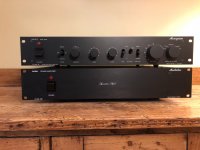
A little while ago I acquired some (as it turns out) fairly rare 70’s cottage industry HiFi kit from Monogram, a Pre-amp and a power amp. Little is documented about this stuff yet reportedly pretty pricey in it’s day it appears well made. The power amp doesn’t work and I’m slowly working on getting that resolved, part of the problem is getting over the claim that Monogram Professional Audio made in their blurb- a “New” and “Exciting” circuit due to its ‘Class A+’ operation, it says it on the front- so it must be true! I gather this is reportedly Class A operation up to a given threshold then AB after that. Bless. …rubbish of course but not understanding the thing or indeed how to bias it, it’s a project for another time…
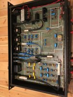
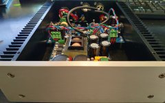
What surprised me was how well built, and good sounding the preamp was; looking inside there’s lots of quality components, big stepped Alps pots and Philips 015 caps- the phono stages (MM and MC) aren’t half bad either. (…is this a Modulus amp build thread? –Ed.) Endearingly we also have fruity text on the front, “Coherent Sound System” “Handcrafted in England” and in italics on the power amp “Studio Reference”… I didn’t just want to leave it at the back of the cupboard somewhere.
Furthermore, and here might be where the astute reader might see where this is going, they come packaged in (nearly) 2U rack enclosures in black- much like the Dissipante line favoured by many of those on this now epic thread.
Attachments
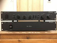
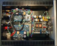
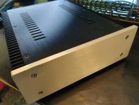
It’s the lockdown in the UK and I fancied a little handcrafting of my own and wanted to build something to match the pre- amp and keep this thing alive- so I’ve re-created the Monogram power amp with Modulus 86 innards after having followed this forum for a while. Front panel layout was to be as similar as possible, though I couldn’t bring myself to write “Studio Reference” on the front… I kept it whimsical and opted for an in-joke with my friends instead, “Signature Style” and “Handcrafted in Kent” where we live.
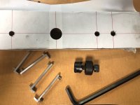
I’ve had great fun doing it- first amplifier build- and credit should be given (of course) to Tom at Neurochrome and also Gianluca at Modushop for quality products, reasonably priced and speedily dispatched, thank you both. Followed Tom’s excellent documentation exactly and everything thankfully went very smoothly. Should also mention I stole the idea for the amp board brackets from a recent build from user Klas- neat…
Sounds great… Thanks again Tom!
Attachments
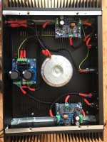
You're welcome. I'm glad it came together nicely for you. Nice work with the front panel. You matched the Monogram style nicely.
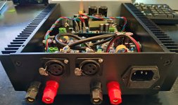
I don't envy the task of poking holes in that steel rear panel. I did that once. That steel is rather hard... It looks like the hole punch worked nicely, though.
That preamp is insane. It looks like the switches are connected to the levers on the front panel by a flexible mechanical link. That's pretty darn cool!
Tom
Mod86 Rebuild
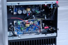
I've been enjoying my Modulus-86 for well over a year. It's actually been running 24/7 since I built it. In post #4510 (Feb 2, 2019) I posted pictures of my completed build. My only complaint was the case was too big. So I stole the SMPS300RE from my LM3886DR build, and found a smaller case on ebay. The smaller ebay case has external dimensions 212mm (w) 70mm (h) x 257mm (d) and internal dimensions 162 (w) x 60 (h) x 246 (d). Much smaller than the Mini Dissipante 2U 300x330 I was previously using.
I actually rebuilt this a few months ago, and am only now getting around to posting pics. And when I came here to post, I see Tom's reply to erozsolt in post #5166 asking about a layout that's essentially the same as what I used:
So, my rebuild is probably a sub-optimal layout. I can't remember exactly why I went with that layout; but I think it's because I thought it would be ideal to try and center the LM3886 chips on the heatsinks. If I pushed the PSU to the back of the case, then the amp chips would definitely not be centered on the heatsinks. Either way, if the layout actually makes a performance difference, I certainly can't hear it.
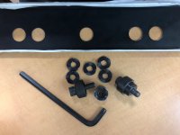
The other kind of ghetto aspect is that I don't have a tapping bit, so I just drilled a hole in the heatsinks, and used a screw and bolt to mate the LM3886 to the heatsinks. The space between heatsink fins is a little too small for the bolt head, so I had to kind of hack at the heatsinks a bit. I had to use a little bit of Aluminum Black to sorta cover up the resulting ugliness. Next time I do something like this, I'll follow Tom's recommendation and actually tap the heatsinks for a nice, neat chip mount.
I've been enjoying my Modulus-86 for well over a year. It's actually been running 24/7 since I built it. In post #4510 (Feb 2, 2019) I posted pictures of my completed build. My only complaint was the case was too big. So I stole the SMPS300RE from my LM3886DR build, and found a smaller case on ebay. The smaller ebay case has external dimensions 212mm (w) 70mm (h) x 257mm (d) and internal dimensions 162 (w) x 60 (h) x 246 (d). Much smaller than the Mini Dissipante 2U 300x330 I was previously using.
I actually rebuilt this a few months ago, and am only now getting around to posting pics. And when I came here to post, I see Tom's reply to erozsolt in post #5166 asking about a layout that's essentially the same as what I used:
What you have will work, but I think it can be improved. Specifically, I would avoid dragging the mains voltage all the way through the chassis. So I'd put the SMPS300RAh towards the back and slide the Modulus-86 modules forward.
I do realize that doing so will put the Modulus-86 off-centre on the heat sink. With only one module per heat sink, that should be fine.
I also recommend keeping the mains rectifier section of the SMPS (so the upper right corner of it in your drawing) away from the input of the amp. That rectifier emits quite a bit of switching noise, so give a good 30-40 mm of separation from anything sensitive (such as the amp inputs).
So, my rebuild is probably a sub-optimal layout. I can't remember exactly why I went with that layout; but I think it's because I thought it would be ideal to try and center the LM3886 chips on the heatsinks. If I pushed the PSU to the back of the case, then the amp chips would definitely not be centered on the heatsinks. Either way, if the layout actually makes a performance difference, I certainly can't hear it.
The other kind of ghetto aspect is that I don't have a tapping bit, so I just drilled a hole in the heatsinks, and used a screw and bolt to mate the LM3886 to the heatsinks. The space between heatsink fins is a little too small for the bolt head, so I had to kind of hack at the heatsinks a bit. I had to use a little bit of Aluminum Black to sorta cover up the resulting ugliness. Next time I do something like this, I'll follow Tom's recommendation and actually tap the heatsinks for a nice, neat chip mount.
Attachments

I've got essentially the same case. Mine however came predrilled with holes for the speaker binding posts and rca and an IEC socket. I however ordered the SMPS300RAh and was sent an SMPS300REh. Difference? Tom was checking that out. I am looking at how I was going to make a hole large enough for the XLRs with the rca socket in the way.
My case also has vent slots on the bottom plate as well similar to the top plate.
Waiting to put everything together and start soldering.
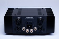
BTW, where is the on off switch?
My case also has vent slots on the bottom plate as well similar to the top plate.
Waiting to put everything together and start soldering.
BTW, where is the on off switch?
Last edited:
BTW, where is the on off switch?
It's that right-most receptacle in the picture of the back of the amp. 😉
I got lazy many years ago and stopped putting power switches on most of my DIY projects, and just use the power plug for turning off and on.
You could get lazier and go to the breaker box and pull the main breaker...the all in one solution.🙂
I actually rebuilt this a few months ago, and am only now getting around to posting pics.
Thank you for sharing your build pictures. It looks like your build came together nicely. I like the compact chassis too.
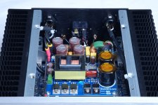
So, my rebuild is probably a sub-optimal layout. I can't remember exactly why I went with that layout; but I think it's because I thought it would be ideal to try and center the LM3886 chips on the heatsinks. If I pushed the PSU to the back of the case, then the amp chips would definitely not be centered on the heatsinks. Either way, if the layout actually makes a performance difference, I certainly can't hear it.
Life doesn't have to be optimal all the time. 🙂 In fact, setting those expectations is probably a recipe for insanity.
As you point out, there are many optimization variables, two being the placement of the LM3886 and the placement of the power supply.
If you have to have the power supply towards the front of the chassis, the placement you have, with the rectifier of the SMPS (the black rectangle sandwiched between a yellow cap and the rightmost of the two black electrolytic caps) as far away from the analog circuitry as possible, is optimal. What I don't like about that placement is that the AC gets strung all the way through the chassis. Tradeoffs, tradeoffs. You can deal with that by keeping the AC wiring away from the inputs to the amps.
That said, I'm also not a fan of putting the LM3886 all the way at the end of the heat sink. I try to stay within the middle third of the heat sink length at least. With the chassis you have, you'd have had one LM3886 almost at the end of the heat sink. That's not such as hot idea either.
Another option would be a mezzanine plate like I did in the Modulus-286 Kit (LE). That adds a lot of complexity on the mechanical side. The Kit was in the 2U x 230 x 200 mm Mini Dissipante.
So... Honestly... I think you picked the lesser evil. Put the lid on it and enjoy the music.
Tom
Attachments

You could get lazier and go to the breaker box and pull the main breaker...the all in one solution.🙂
And that would probably also save me money on my electrical bill. It's win-win!
With the chassis you have, you'd have had one LM3886 almost at the end of the heat sink. That's not such as hot idea either.
It may be a "hot" idea, in the literal sense. 😉
Put the lid on it and enjoy the music.
Done! I think that's the truly optimal solution.
Is there a functional difference between using the Antek AN-2222, AS-2222, or Hammond
1182N22 on the Power-86?
1182N22 on the Power-86?
Not really.
Some may argue that 160 vs 200 VA puts the Hammond at a disadvantage as it could in theory result in greater rail sag, but the difference is negligible (if there at all). Besides, due to its error correction circuit, the Modulus-86 handles rail sag better than regular amps. With the LM3886DR, the effect would be more pronounced, but we're really in the dBGF territory in my view. That's dB relative to one imperial Gnat Fart, by the way. 🙂
I would argue that the Hammond transformer is a better quality transformer. At least judging by pictures, the windings on the Hammond are much tighter than on the Antek. Thus, I would expect the Antek to have a higher leakage field, which would put it at a disadvantage.
That said, Antek is tough to beat on price ... at least if you're in the US.
Tom
Last edited:
So the 200VA vs 160VA is a negligible difference between the Antek and the Hammond, and I shouldn't really notice the difference on the LM3886DR?
What about the electrostatic shield between the primary and secondary that the Antek has?
Being in Canada and being able to get the Hammond from Mouser is easier than getting the Antek from the USA.
P.S. I did really Google the crap out of this line of questions both here and in general and didn't come up with much, so I hope this will help other noobs as well... 🙂
Last edited:
So the 200VA vs 160VA is a negligible difference between the Antek and the Hammond, and I shouldn't really notice the difference on the LM3886DR?
Correct.
What about the electrostatic shield between the primary and secondary that the Antek has?
The shield would shunt RF energy on the mains to ground. If you're concerned about RF on the mains, you could also filter it out with an IEC inlet filter.
If you were building a frontend for an EKG or EEG amplifier, I would see maybe wanting the electrostatic shield, but. I'm not sold on its advantages in a power amp. That said, I don't think it costs extra at Antek, and I don't see any harm of using it, so if you shop at Antek, get the shield. I think that also gets you a "belly band" (GOSS band), which minimizes leakage fields.
Note that I make most of my measurements with the amplifier board sitting on my lab bench (attached to a 0.4 K/W heat sink). If I use a transformer with a shield, the shield is normally floating as I don't have a chassis to ground it to.
P.S. I did really Google the crap out of this line of questions both here and in general and didn't come up with much, so I hope this will help other noobs as well... 🙂
Sounds like an opportunity for me to add to the Taming the LM3886 series. 🙂
Tom
Last edited:
- Home
- Amplifiers
- Chip Amps
- Modulus-86 build thread