Basic question about thermal dissipation best practices. When using the insulated LM3886TF chip is it a good idea to still use thermally conductive grease between the chip and heat sink? Since it is insulated I just bolted it directly to the heat sink but after reading some other posts about heat management I thought that may not be the best approach for heat transfer and grease would be beneficial. One thing I also did was make custom washers to spread the bolt load out over the whole tab better.
I believe the LM3886TF is electrically insulated, not thermally. Yes to using heat transfer compound.
If you look closely at the LM3886TF, you'll notice that its surface has a little bit of texture to it. This means you'll get air pockets between the package and the heat sink. Air is not very thermally conductive.
The purpose of thermal compound or thermal grease, otherwise known as "goop", is to fill those little air pockets. Thermal compound isn't very thermally conductive either, but it's a lot more thermally conductive than air. Just note that you only want enough to fill the air pockets.
I generally smear the goop on with a finger and then run the sharp edge of a utility knife blade across to remove the excess. Do the same with the heat sink in the area where the LM3886 will sit. Then bolt the two together.
I generally recommend Wakefield 120 thermal grease. The '126' is good too. The difference between the two is that the '126' is more tolerant of flux cleaners, thus is a bit better in a production environment. I seem to recall that it's also a bit more expensive.
If you don't have plans for a Mouser/Digikey order any time soon, you can find thermal grease at your local computer hardware/repair place. Arctic Silver is a common brand. Expect to pay more at the computer place than you would at Mouser/Digikey, though.
Also note that with the LM3886T (non-insulated metal back version) you need to provide electrical insulation between the metal back and the heat sink. Otherwise, you'll short the V- supply to ground via the heat sink and instantly blow the thermal relief on the board and the bond wire to the V- pin inside the package. (Yes, I did that on an LM4780 in one of the prototype experiments leading to the Parallel-86 "back in the day" 🙂). For the metal back version of the LM3886, I recommend the Keratherm Red (86/82) pads. You can get them from me or from the DIY Audio Store.
Tom
Last edited:
I believe the LM3886TF is electrically insulated, not thermally. Yes to using heat transfer compound.
Yes you should use a thermal grease.
Thanks, I applied some thermal grease between the chips and heat sinks as well as a bit of insulation around some leads Tom mentioned should have a little more protection. It's all buttoned up again and playing music.
Hi, I've opened a thread related to crimping tools for my Modulus build. Since I see so many nice builds here, I'm sure many of you have lot of experience with this. I'd be happy to hear what you say.
https://www.diyaudio.com/forums/equ...ed-quick-disconnects-fastons.html#post6193808
https://www.diyaudio.com/forums/equ...ed-quick-disconnects-fastons.html#post6193808
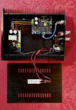
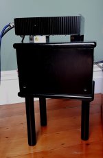
First time posting on any forum but here is my build of the Modulus 86.
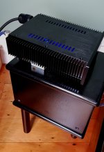
Built them as small monoblocks to sit directly on the external xovers meaning I don't need any extra speaker cables - YAY! The xovers have short 'tails' straight up to the binding posts of the amps.
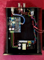
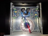
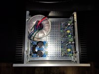
For those (all?) of you who like construction details I used the Connex SMPS240QR power supplies as easy and seem more than capable and absolutely dead quiet with my high 90's sensitivity speakers.
Amps run at only just above ambient with only a slight temp rise when playing loud. Of course my 8 ohm speakers don't need much power though......
Only variation was replacing the 20k feedback resistors with Charcroft Z-foils - just liked the idea.
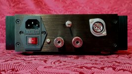
Connectors chosen were Viborg because I like rhodium plating and the teflon XLRs seem well made. Certainly can't fault them but there are lots of other choices out there!
Internal IC wiring is the Swiss Gotham top reussen bal cable. Fiddly to use but gets top comments in the pro world. Very reasonably priced too.
Short output cable is Duelund silver foil.
Because the amps are directly behind the speakers I decided to place LEDs under the lid to 'wash' colour through the ventilation slots. Amber + blue + off - completely silly I know but colour selection depending on mood and a good reminder the amps are on.
The monos meant a complete change in direction for me as I could go balanced for the first time from my DAC. Of course that meant new ICs (3.5m Gotham mentioned above) and new power cables (decided to go with Gothams top reussen screened PC too). I have absolutely no idea how the Gothams stack up against my traditional 'audiofoolery' stuff as I don't have ready access to such long lengths. All I can say is the system is performing considerably better than it has ever done - amazing 3D imaging, super detailed and tonally very nice. Excellent, actually far superior bass control and dynamic contrasts in spite of its low power rating against my other 125W highly regarded amp. Certainly wouldn't be embarrassed by some of the exotica I have heard at RMAF and the Munich shows IMHO.
It is really great to be able to build such high performing pieces of kit yourself. Thanks to Tom for releasing them and my friend Tim for allowing me to hear his 86 and get me motivated again!
Built them as small monoblocks to sit directly on the external xovers meaning I don't need any extra speaker cables - YAY! The xovers have short 'tails' straight up to the binding posts of the amps.
For those (all?) of you who like construction details I used the Connex SMPS240QR power supplies as easy and seem more than capable and absolutely dead quiet with my high 90's sensitivity speakers.
Amps run at only just above ambient with only a slight temp rise when playing loud. Of course my 8 ohm speakers don't need much power though......
Only variation was replacing the 20k feedback resistors with Charcroft Z-foils - just liked the idea.
Connectors chosen were Viborg because I like rhodium plating and the teflon XLRs seem well made. Certainly can't fault them but there are lots of other choices out there!
Internal IC wiring is the Swiss Gotham top reussen bal cable. Fiddly to use but gets top comments in the pro world. Very reasonably priced too.
Short output cable is Duelund silver foil.
Because the amps are directly behind the speakers I decided to place LEDs under the lid to 'wash' colour through the ventilation slots. Amber + blue + off - completely silly I know but colour selection depending on mood and a good reminder the amps are on.
The monos meant a complete change in direction for me as I could go balanced for the first time from my DAC. Of course that meant new ICs (3.5m Gotham mentioned above) and new power cables (decided to go with Gothams top reussen screened PC too). I have absolutely no idea how the Gothams stack up against my traditional 'audiofoolery' stuff as I don't have ready access to such long lengths. All I can say is the system is performing considerably better than it has ever done - amazing 3D imaging, super detailed and tonally very nice. Excellent, actually far superior bass control and dynamic contrasts in spite of its low power rating against my other 125W highly regarded amp. Certainly wouldn't be embarrassed by some of the exotica I have heard at RMAF and the Munich shows IMHO.
It is really great to be able to build such high performing pieces of kit yourself. Thanks to Tom for releasing them and my friend Tim for allowing me to hear his 86 and get me motivated again!
Attachments
Hey! Welcome to DIY Audio. That's a very nice build there. I'm glad it came together nicely for you.
It's also the first time I see the Connex SMPS240QR in action. That's a nice option for mono blocks for sure.
Looks like one of the BZ... chassis from eBay?
Tom
It's also the first time I see the Connex SMPS240QR in action. That's a nice option for mono blocks for sure.
Looks like one of the BZ... chassis from eBay?
Tom
Thanks for the welcome Tom.
The 240W Connex supply worked out well in the case although could have gone with the 300W version - better, who knows!? The mono amps are perfect for me too as am over speaker cable dramas..... My wife is happy as less clutter.
Case is the BRZHIFI BZ2107 series double radiator aluminum case for DIY on Aliexpress and very reasonably priced from Weiliang Audio. Am sure it is available from other sites too.
Hoping to hear your line/buffer stage here as my friend thinks it is better than going direct from his DAC.
My wife is happy as less clutter.
Happy wife, happy life. 🙂
Case is the BRZHIFI BZ2107 series double radiator aluminum case for DIY on Aliexpress and very reasonably priced from Weiliang Audio. Am sure it is available from other sites too.
I usually find them from a wide range of vendors on eBay. The all seem to cost the same too by the time shipping is factored in.
My 4x Modulus-86 amp is in a BZ4309. I did find that they could have cleaned it up better before shipping, though. Many of the panels were coated in cutting oil and the corner posts needed de-burring. It wasn't a huge deal to clean it up, but I had expected a bit better. It looks good once assembled, though.
Hoping to hear your line/buffer stage here as my friend thinks it is better than going direct from his DAC.
Nice!
Tom
Stereo Modulus-86 build in Mini Dissapante 330x200
Howdy All,
What would be considered the better component layout for a stereo Modulus-86 build in Mini Dissapante 2U 330x200?
AS2222 Toroid in front with symmetric board placement or asymmetric with both driver boards on one side? Those heatsinks are 200x80x40mm.
I am not too worried about heat since this is a near-field desktop setup driving Micca RB42 speakers (~6 ohms).
My existing stereo LM3886 amp (AS2210) is symmetric and the heatsinks are 150x60x25mm and is barely above room temp after running all day in a 75f room.
Thanks,
Bryan
Attachments

What would be considered the better component layout for a stereo Modulus-86 build in Mini Dissapante 2U 330x200?
Great. Now I'm getting chassis envy again. 🙂 I really like that chassis and the compact builds that can be had with it.
Are you sure it's not the 330 x 250 mm chassis you have? The useful internal dimensions look to be 250x250 mm based on the board sizes.
Personally, I prefer the arrangement with one MOD86 per side for better heat distribution.
That said, for casual use it doesn't matter much. Even for sine wave operation into a 4 Ω load, the 0.47 K/W of the Mini Dissipante 2Ux250 mm heat sinks will provide enough cooling for the amp to survive continuous operation with both channels going.
Tom
Bryan , I don't want to upset you, but your modulus86 components look like they are about to get soldered , to avoid cold joints I would resolder all the components at the top of the boards too.
Gabe
Gabe
The boards are through-plated. I.e. each hole has a metal 'sleeve' in it that connects top and bottom layer. I wouldn't worry about soldering both top and bottom.
You do want to use enough solder that it wicks up into the hole, but you don't need so much that it puddles on the top.
Tom
You do want to use enough solder that it wicks up into the hole, but you don't need so much that it puddles on the top.
Tom
Hi Tom,
I am planning a potential 3 way active speaker project (ATC clones).
I am busy designing the active XO pcb's and I envision the following configuration:
Each speaker will have an active XO board and 3 Mod86 boards.
There will be one main unreg PSU feeding the 3 Mod86s and a +/-15V Reg PSU for the XO board.
The XO board is opamp based, has THAT120x balanced in and high/mid/low unbalanced out.
Any reason why I shouldn't leave out the THAT1200s on the Mod86 boards and take my signals straight into LM49720s?
The +/-15V Reg PSU for the XO board will be fed from the main amp PSU rails, the 0v on the XO board will connect to all the Mod86 "input gnd"s via the signal 0v only (which I see are connected to the main 0v on each Mod86 board at the output gnd).
The 0v chassis connection will be at the main amp PSU.
Would there be any advantage / disadvantage to not populating the +/-15regs on the Mod86 boards and running all the Mod86 opamps along with the XO on a common regulated supply?
Any other obvious implementation issues / problems that I'm missing?
Thanks,
John
I like configuration in the first picture. At least this is how my amps are payed out. But have thought about trying the layout in the last picture.
Reasons why;
The layout shown in the first picture minimizes the length of the input and output cables. Less antenna effects.
The layout in the third picture minimizes the length of the input AC leads. Less field generated.
Almost all commercial amps look like first picture. Assume people have built all three and found this measures better.
Not Tom, but isn't using equally-rated amplifiers on every driver of an active three-way highly unusual?Any other obvious implementation issues / problems that I'm missing?
If you were to minimize the cost then that is the case. In commercial applications of active systems, one of their requirements is to not supply too much amplification for sections that don't need it only for amplifier cost reasons. They can use multiple smaller amps to supply the total power required.Not Tom, but isn't using equally-rated amplifiers on every driver of an active three-way highly unusual?
In this implementation, I can see the convenience of just using the same transformer and let the amps share it. The MOD86 can tolerate that without detrimental effects as long as there is sufficient VA available.
My belief there is never excess headroom.
Each speaker will have an active XO board and 3 Mod86 boards.
There will be one main unreg PSU feeding the 3 Mod86s and a +/-15V Reg PSU for the XO board.
The XO board is opamp based, has THAT120x balanced in and high/mid/low unbalanced out.
Any reason why I shouldn't leave out the THAT1200s on the Mod86 boards and take my signals straight into LM49720s?
Excellent project. If you want a single-ended input, you can simply connect pin 3 to pin 6 on the THAT1200 footprint. Then connect the input signal to pin 1 (GND) and pin 2 (IN+) on the MOD86.
Any other obvious implementation issues / problems that I'm missing?
Not that I can tell.
As pointed out above, you might be able to further optimize the design by going with Modulus-86 on the 8 Ω drivers and Modulus-286 on the 4 Ω drivers and using ±35-36 V supply voltage. That would give you more output power. If 40 W into 8 Ω, 65 W into 4 Ω is sufficient for your needs, what you describe will work well.
Tom
- Home
- Amplifiers
- Chip Amps
- Modulus-86 build thread