Right now I am using no preamp. I have a phono section plugged straight into the amp.
That's the problem. Many phono stages only provide a few hundred mV of output on average records. You need a preamp with a bit of gain.
Tom
As I said I have perfectly deliberately not touched the electronics, so yes I am asking for optimal circuit values as determined by Tom's testing.Just to be clear as this could be misread. You are not asking Tom to read the app notes for you and check that Behringer built it with recommended values to get spec sheet performance? I assume you have done that already?
Dan.
As I said I have perfectly deliberately not touched the electronics, so yes I am asking for optimal circuit values as determined by Tom's testing.
The optimal values are in the LM3886 data sheet, actually. The only thing I disagree with National on is the Thiele network. I use a bit more inductance than they do. Everybody seems to be stuck on 10 Ω for the dampening resistor. That's way too much. I suggest aiming for a Q of 1.0 around 200 kHz.
I suspect this information will make it onto my Taming the LM3886 pages at some point. I have a few other irons in the fire right now, though.
Tom
Thanks Tom, that's all the info that I need.
The Behringer schematic is close but omits the inputs shunt cap, and the output shunt zobel, which I will fit at the driver terminals.
Dan.
The Behringer schematic is close but omits the inputs shunt cap, and the output shunt zobel, which I will fit at the driver terminals.
Dan.
The Zobel/snubber needs a low impedance connection from the amp output through the Zobel to the local decoupling ground by the LM3886. Placing the Zobel network at the speaker terminals is the highest impedance path possible.
Without Cc, the amp will go into quasi-oscillation (buzz) near clipping. I'm surprised Behringer omitted the cap given that they have Rf2 and Cf in there.
Anyway. If you'd like to discuss this further, we should probably move to a separate "Pimp my Monitor" thread. 🙂
Tom
Without Cc, the amp will go into quasi-oscillation (buzz) near clipping. I'm surprised Behringer omitted the cap given that they have Rf2 and Cf in there.
Anyway. If you'd like to discuss this further, we should probably move to a separate "Pimp my Monitor" thread. 🙂
Tom
Tom,
Thanks for the info on the LED installation. It''s done, works great and just as you said...no noise or thump. I measured the voltage at the LED and it's 1.7 which is very good because I think the spec. recommends 1.8. Maybe the -.1 margin will make it last a bit longer. I also measured the voltage on the + and - rails and both are exactly 32.8.
Also I was going to make two spring clamps for the lm3886s but saw your pic with the aavid clamp. $0.40 and a hole drilled in each, that will allow use of the already tapped heatsink holes that are aligned with the lm3886 tab holes, and done.
The hole will be located such that the clamp will apply pressure on the middle of the thicker main body. I've got a very small torque wrench that will be perfect for the 4-40 allen head cap screws I'm using.
A small hand held fish scale and some fishing line and I can set the pressure on the lm3886 to the spec. sheet number.
Thanks for the info on the LED installation. It''s done, works great and just as you said...no noise or thump. I measured the voltage at the LED and it's 1.7 which is very good because I think the spec. recommends 1.8. Maybe the -.1 margin will make it last a bit longer. I also measured the voltage on the + and - rails and both are exactly 32.8.
Excellent! The voltage across the LED is not critical. It depends on the current through the LED and the temperature of the LED in addition to the semiconductor materials used in the LED. I'm sure you'll get your 50k+ hours of operation out of it.
Also I was going to make two spring clamps for the lm3886s but saw your pic with the aavid clamp. $0.40 and a hole drilled in each, that will allow use of the already tapped heatsink holes that are aligned with the lm3886 tab holes, and done.
Bingo!
A small hand held fish scale and some fishing line and I can set the pressure on the lm3886 to the spec. sheet number.
I'm amazed by your ingenuity, but you're way overanalyzing this. All you have to do is to line up the clip with the LM3886 body and drive a screw through the hole in the clip. Tighten the screw all the way and let the clip do its job. The clip is designed to provide the appropriate amount of pressure when used this way.
Tom
Thanks Tom. I will pm you shortly.That's the problem. Many phono stages only provide a few hundred mV of output on average records. You need a preamp with a bit of gain.
Tom
Actually it is a bit too loud. I normally use a dc coupled b1 buffer. It has unity gain. With amps that have 26dB gain it's about 3/4:up. No preamp gain required.
The phono section has op-amp outputs. Op627.
I will run near end and far end zobels.The Zobel/snubber needs a low impedance connection from the amp output through the Zobel to the local decoupling ground by the LM3886.
Placing the Zobel network at the speaker terminals is the highest impedance path possible.
Yeah, I'm surprised too.Without Cc, the amp will go into quasi-oscillation (buzz) near clipping. I'm surprised Behringer omitted the cap given that they have Rf2 and Cf in there.
Plenty of capacitor types to experiment with.
Sure, and thanks.Anyway. If you'd like to discuss this further, we should probably move to a separate "Pimp my Monitor" thread. 🙂
Dan.
tomchr; The clip is designed to provide the appropriate amount of pressure when used this way. Tom[/QUOTE said:The Aavid clip is designed to be mounted as you did. I want a clip that will mount via the lm3886 hole and my already tapped heatsink holes.
I don't want to remove the heatsinks and tap new holes. I'm lazy.
So, after hours of web searching, I found the HALA company that makes all sorts of things for electronics, including their HALA-CLIP TO-220-1. It looks perfect and will mount via the lm3886 hole after, maybe, a 1 or 2mm elongation of the clip mounting hole...simple small round hand file or Dremel. This is to move the clip contact such that it's is closer to the center of the chip. That is farther away from the end where the leads sprout.
Forget the Fish scale...just a small torque wrench, I have, that will fit between the heatsinks...no removal of anything but the screws.
Their distributors are in many European countries but not the US. I sent some emails and hope to hear from at least one of them.
Regarding the 5.6kohm chassis mount resistor, it stays cool to the touch after several hours of continuous play. Must be the flattening of the mounting surfaces and thermal grease doin their job.
I found the value of Cc strongly depends on the input impedance the +IN is seeing. High source impedance is dangerous with 220pF.Without Cc, the amp will go into quasi-oscillation (buzz) near clipping.
If the rise in 1/beta associated with Cc kicks in too early it tends to destabilize the amp because the intersect with Aol isn't flat enough, reducing phase margin. Cf and Rf2 counteract the 1/beta rise but if the corner frequencies are not right things may go wrong.
The Aavid clip is designed to be mounted as you did. I want a clip that will mount via the lm3886 hole and my already tapped heatsink holes.
As long as you realize that you are trying to solve a problem that is not there. The way you have the LM3886 mounted to the heat sink is exactly the way National intended it. You will not get any benefit at all by using a clip.
The amp is working according to spec. Why mess with it? I mean... It's your amp, your time, and your money, so you're free to do whatever. Please don't create more work for me in the process. If it ain't broken, I strongly discourage you from trying to fix it.
Tom
Last edited:
I found the value of Cc strongly depends on the input impedance the +IN is seeing. High source impedance is dangerous with 220pF.
If the rise in 1/beta associated with Cc kicks in too early it tends to destabilize the amp because the intersect with Aol isn't flat enough, reducing phase margin. Cf and Rf2 counteract the 1/beta rise but if the corner frequencies are not right things may go wrong.
Yep. And if the source impedance is too low, you get feed-through through Cc causing a peak in the closed loop frequency response.
Tom
As long as you realize that you are trying to solve a problem that is not there. The way you have the LM3886 mounted to the heat sink is exactly the way National intended it. You will not get any benefit at all by using a clip.
The amp is working according to spec. Why mess with it? I mean... It's your amp, your time, and your money, so you're free to do whatever. Please don't create more work for me in the process. If it ain't broken, I strongly discourage you from trying to fix it.
Tom
I just ran across a National pdf file and they say what you said. Mount via the screw hole. They show diagrams, sketches and pics of the internal components and I can see why only a screw through the tab hole is needed and recommended. A fairly substantial metal piece runs from top to bottom and the area where the die sits appears even thicker.
They, or some other pdf, said pressure on the die, in lm3886tf is not not needed or recommended.
I've measured temps on the heatsinks and they have rarley reached 90F and the chips feeler and measure even cooler. I have to admit that I don't think there will be any heat related chip movement. If anything I may only use a slightly larger diameter flat washer that will apply press around the tab hole and extend slightly over, and apply some pressure on, the angled edge where the thicker body portion begins.
Why did you choose to use the Aavid clip? I think you mentioned you got very good measured power.
Thanks,
Henry
The larger washer is just belt and suspenders as I think it will run hotter with the b&w n803s in the much larger room where I sit about 12 feet away from the speakers.
Also one of the pdfs had a section on potential chip rotation, which could damage the leads internally, when tightening the screw.
I used two very smooth .02 thick flat washers topped with a lock washer. I didn’t see or feel any rotation during tightening.
I think a good result of the LED installation is it feels cool. I think the light press fit in the hole in the 3/8” thick panel is acting like a heatsink.
Henry
Last edited:
I just ran across a National pdf file and they say what you said. Mount via the screw hole. They show diagrams, sketches and pics of the internal components and I can see why only a screw through the tab hole is needed and recommended. A fairly substantial metal piece runs from top to bottom and the area where the die sits appears even thicker.
Bingo!
They, or some other pdf, said pressure on the die, in lm3886tf is not not needed or recommended.
I don't recall anything like that. You can't access the die in the LM3886 anyway. It's completely encapsulated in the plastic.
If anything I may only use a slightly larger diameter flat washer that will apply press around the tab hole and extend slightly over, and apply some pressure on, the angled edge where the thicker body portion begins.
You do NOT want the washer to be sitting on an edge. You want the washer flat against the tab of the LM3886TF. I use a regular M3 flat washer to ensure that the pressure from the mounting screw is uniformly distributed around the slightly larger mounting hole in the LM3886TF.
Why did you choose to use the Aavid clip? I think you mentioned you got very good measured power.
I use the clip because it makes mounting easier. I get the same output power with the clip as I get with screw mounting.
Just because there is more than one way to get good results does NOT mean that you need to change anything. There are many other builders reading this thread. The fact that I post new findings is NOT an indication that any action is needed on your part. I simply post those details to make others benefit from my findings. Should you benefit also, that's great. However, there is NO need for you to change anything at all at this time.
Tom
AlexQS, I'm late to the thread, but gorgeous looking amp! Congrats
Thanks. Waiting for SpeakON panel mount plugs now, hoping to finish wiring and rearpanel cutouts this weekend. 🙂 soon will be listening time!
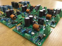
I've just finished the build of six Modulus-86 boards. Initially they were for a LX521 build but they have now been redirected to a church organ replacement project using a dozen drivers from Common Sense Audio. I have one or two joints to check over. Otherwise the build has gone very well indeed. Thanks Tom for a wonderful kit!

Last edited:
- Home
- Amplifiers
- Chip Amps
- Modulus-86 build thread