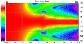
How much is enough? I've been doing a lot of active cardioid sims in Vituix and I find its very hard to get much rejection to the side. Rejection to the rear of the box can be quite goo, however. This is the best I've been able to do with side drivers on a 320mm wide box. The side drivers are high passed at 100 Hz to minimize excursion requirements.
Attachments

Nice plot. Is that a single driver in the front and one driver each side? I bandpass and time delay the control drivers as well.
Good enough would be -6dB of the sides and -9dB on the back.
Good enough would be -6dB of the sides and -9dB on the back.
I wish it were just a couple of drivers.. I've got an 200 cm dia. waveguide/CD playing 1200 Hz up. spaced evenly around its rim and playing through slots are 4 small drivers that are good down to 100 Hz and extend the directivity down to perhaps 600 Hz. On each side I have two 6.5" woofers. I can use them as subs or play them inverted and delayed to get the cardioid like response shown. The sim is showing 6-8 db to the sides and 15-20 db to the rear so I would say your goals are achievable.
A more interesting question to me is why 6-8 db to the sides and -9db to the rear are enough. I was surprised at first that even with the directivity I had, I still got boundary nulls. All the added directivity did was reduce the depth of the side nulls by a couple of db. Looking at the angle to the first reflection points, I see it would have to be a very tight beam indeed to eliminate the nulls completely. I have tuned for a gradual transition of directivity from omni bass to cardioid low mid. If I tuned for a sharp transition I would get higher directivity in the region but the power response wouldn't be as nice. I concluded that the right thing to do was tune for a "nice" power response and PIR. I changed the vertical stripes of 3" drivers I originally had on the sides to pairs of 6.5" woofers that turned out to work equally well as subs or for cardioid response but only down to 100 Hz limited by the excursion of my "horn mouth edge port" drivers.
Yeah if inspecting single reflection only it is quite easy to check out what is needed to get the resulting interference less. About 10db attenuation towards the reflection is needed (well, the reflected signal needs to be attenuated, could be room treatment as well) to get nulls "only ~6db". 20db attenuation makes the interference to ~+/-1db which I think starts to be inaudible. This is the goal I think, but very hard to achieve unless very narrow pattern.


The response can be optimized (like supercardioid) so we can have -20db or more attenuation towards some angles, towards the reflection point, but it is hard to get wide bandwidth, notch is easy. IF we only have a notch like attenuation it doesn't do much, or perhaps even makes the situation worse (speculating that hearing system can mostly ignore the interference if it resembles the direct sound).
Here is reflected signal with EQ dip strategically positioned to a null. It kills tip of the null but right next to it the interference stays as the attenuation wears off. We gotta remember that next to a null is constructive interference as well!

Perhaps any attenuation is good and all we really have to do is to help the brain to filter the reflections out from perception. Interesting question is how we achieve this, how to help the brain? Perhaps attenuation is not as important (so that any attenuation is fine) as keeping the reflection same as direct sound?
We have to remember the reflections don't happen alone but there are plenty which all combine. If one makes similar test but with several reflections it is clearly seen that the reflections "overpower" listening position response over the direct sound. Direct sound is just one signal, and if there is 6 first reflections from room boundaries with different frequency response the resulting response looks more like the reflections and not the direct sound. What basically happens we arrived to the power response. Anyway, it is interesting excercise to figure out if some of these reflections are bad for perceived sound and how to make them less bad, even though the power response was nice. Perhaps try make smooth ERDI to prioritize first reflections over other directions.
The response can be optimized (like supercardioid) so we can have -20db or more attenuation towards some angles, towards the reflection point, but it is hard to get wide bandwidth, notch is easy. IF we only have a notch like attenuation it doesn't do much, or perhaps even makes the situation worse (speculating that hearing system can mostly ignore the interference if it resembles the direct sound).
Here is reflected signal with EQ dip strategically positioned to a null. It kills tip of the null but right next to it the interference stays as the attenuation wears off. We gotta remember that next to a null is constructive interference as well!
Perhaps any attenuation is good and all we really have to do is to help the brain to filter the reflections out from perception. Interesting question is how we achieve this, how to help the brain? Perhaps attenuation is not as important (so that any attenuation is fine) as keeping the reflection same as direct sound?
We have to remember the reflections don't happen alone but there are plenty which all combine. If one makes similar test but with several reflections it is clearly seen that the reflections "overpower" listening position response over the direct sound. Direct sound is just one signal, and if there is 6 first reflections from room boundaries with different frequency response the resulting response looks more like the reflections and not the direct sound. What basically happens we arrived to the power response. Anyway, it is interesting excercise to figure out if some of these reflections are bad for perceived sound and how to make them less bad, even though the power response was nice. Perhaps try make smooth ERDI to prioritize first reflections over other directions.
Last edited:
re' killing a notch with strategic eq
The original notch is sharp and deep - the kind whose null is most likely to be filled with ambient sound field. This and the fact that it is narrow makes it less likely to be audible. While the EQ made it quite shallow by comparison, it also made it wider which would make it more audible. On top of that the efficacy of the EQ is highly listening position dependent.
In Vituix, you can enable first reflections from 3 surfaces. The room has 6 reflecting surfaces and multiple reflections which are reasons beyond preference rating to keep the reflections disabled most of the time and go by the power response and pir curves. But you can only do that in the real world with a full set of polars.
A more interesting question to me is why 6-8 db to the sides and -9db to the rear are enough. I was surprised at first that even with the directivity I had, I still got boundary nulls. All the added directivity did was reduce the depth of the side nulls by a couple of db. Looking at the angle to the first reflection points, I see it would have to be a very tight beam indeed to eliminate the nulls completely. I have tuned for a gradual transition of directivity from omni bass to cardioid low mid. If I tuned for a sharp transition I would get higher directivity in the region but the power response wouldn't be as nice. I concluded that the right thing to do was tune for a "nice" power response and PIR. I changed the vertical stripes of 3" drivers I originally had on the sides to pairs of 6.5" woofers that turned out to work equally well as subs or for cardioid response but only down to 100 Hz limited by the excursion of my "horn mouth edge port" drivers.
I wanted something monopole with pronounced forward lobe even at low freq. I'd be happy with DI >4 so the power response (100-300Hz) is closer to the rest of the horn system. Added feature of less reflections. It's been like pushing on a cloud, but I think I have something close now (pics in a few posts). I could not get what I wanted from drivers near the horn mouth. Its tricky to get the mag and phase tuned, especially with 4 sides active otherwise something is always flawed.
Thorough post, they look like dipole nulls.Yeah if inspecting single reflection only it is quite easy to check out what is needed to get the resulting interference less. About 10db attenuation towards the reflection is needed (well, the reflected signal needs to be attenuated, could be room treatment as well) to get nulls "only ~6db". 20db attenuation makes the interference to ~+/-1db which I think starts to be inaudible. This is the goal I think, but very hard to achieve unless very narrow pattern.
View attachment 1048920View attachment 1048919View attachment 1048918View attachment 1048917View attachment 1048916
The response can be optimized (like supercardioid) so we can have -20db or more attenuation towards some angles, towards the reflection point, but it is hard to get wide bandwidth, notch is easy. IF we only have a notch like attenuation it doesn't do much, or perhaps even makes the situation worse (speculating that hearing system can mostly ignore the interference if it resembles the direct sound).
Here is reflected signal with EQ dip strategically positioned to a null. It kills tip of the null but right next to it the interference stays as the attenuation wears off. We gotta remember that next to a null is constructive interference as well!
View attachment 1048926
Perhaps any attenuation is good and all we really have to do is to help the brain to filter the reflections out from perception. Interesting question is how we achieve this, how to help the brain? Perhaps attenuation is not as important (so that any attenuation is fine) as keeping the reflection same as direct sound?
We have to remember the reflections don't happen alone but there are plenty which all combine. If one makes similar test but with several reflections it is clearly seen that the reflections "overpower" listening position response over the direct sound. Direct sound is just one signal, and if there is 6 first reflections from room boundaries with different frequency response the resulting response looks more like the reflections and not the direct sound. What basically happens we arrived to the power response. Anyway, it is interesting excercise to figure out if some of these reflections are bad for perceived sound and how to make them less bad, even though the power response was nice. Perhaps try make smooth ERDI to prioritize first reflections over other directions.
I'm not sure I understand the simulation you ran (drivers, room, positions, etc).
[edit] It's initially more about the power response and DI matching to the rest of the horn.
Last edited:
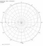
V14-5 with control drivers on the rear and sides. Could use some on axis EQ, but it's getting closer.
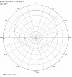
[edit] - I think the attn on the sides could be further improved though tuning. The polar @300Hz is the goal.
[edit] - I think the attn on the sides could be further improved though tuning. The polar @300Hz is the goal.
Attachments
-
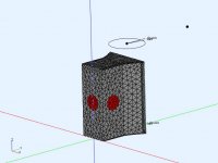 V14-5 RearSideDrivers Model.jpg33.6 KB · Views: 131
 -
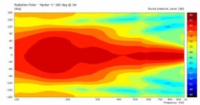 V14-5 RearSide - Hpolar.jpg28 KB · Views: 136
 -
 V14-5 RearSideDrivers Hpolar 100Hz.jpg46.9 KB · Views: 124
 -
 V14-5 RearSideDrivers Hpolar 150Hz.jpg47.5 KB · Views: 134
 -
 V14-5 RearSideDrivers Hpolar 200Hz.jpg48.2 KB · Views: 128
 -
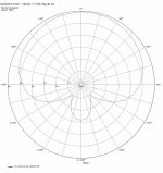
 V14-5 RearSideDrivers Hpolar 300Hz.jpg47.8 KB · Views: 137
Last edited:
It is simulation of two sources, the other moved a bit further back to make interference pattern at inspection point as they two combine making constructive and destructive interference depending on wavelenght and phase relationship. It is ideal situation trying to mimic perfect source and one reflection. It then illustrates narrowing output pattern by attenuating "the reflection". It is easy to inspect the result by looking at the interference pattern and ***** how much the reflection affects to the direct signal. This doesn't tell how we would perceive the sound, it is just phenomenon that happens when two signals interact.Thorough post, they look like dipole nulls.
I'm not sure I understand the simulation you ran (drivers, room, etc). How can a -10dB reduction only have a 1dB net effect ?
As the illustration shows attenuating signal -6db towards reflection point we still get almost as much interference at inspection point and could interpret that it is about as audible as without attenuation.
OK thanks, that's perfectly clear, Two sources creating interference patterns (dipole) to emulate a reflection. You had me wondering about distances and wall models used.
V14-5 with control drivers on the rear and sides. Could use some on axis EQ, but it's getting closer.
[edit] - I think the attn on the sides could be further improved though tuning. The polar @300Hz is the goal.
Thinking. You might be able to fine tune pattern at 300Hz by manipulating width of the back, perhaps losing the back driver or just by using the back driver alone, to reduce pathlenght between them. You are probably not going to be able to remove (the widening, now at 300Hz) it but can slide it up or down in frequency.
I suspect the back would be needed to made much smaller than the horn mouth, perhaps pointy, to move the widening to the horn mouth wavelenght so the horn makes it disappear. Or make the back(enclosure) wider (mouth width) and shallower perhaps, if you want to retain the volume. One driver on the back perhaps to tune the pattern.
Both smooth cardioidish pattern speakers I know have narrow baffle and quite deep enclosure though, Kii three and D&D 8c. Hence not sure what works in your case, until experimenting.
Last edited:
At 300Hz it's mostly just the horn radiating, the side and rear control drivers are nearly off, and I'm happy with that. There is a tricky balance trying to squeeze the region 100-299 Hz to look more like the 300Hz polar. After many iterations I've concluded that I need both side and rear drivers if a square box is used.
In line with your "pointy" back idea, it would be interesting to use just 2 drivers mounted on either side of the point (45deg, 60deg? point). It would be like combining the rear and sides. It could make the implementation alot easier. I have done simulations on models like the 8c but it's passive side ports don't provide enough control. I also want to keep the sealed woofers.
In line with your "pointy" back idea, it would be interesting to use just 2 drivers mounted on either side of the point (45deg, 60deg? point). It would be like combining the rear and sides. It could make the implementation alot easier. I have done simulations on models like the 8c but it's passive side ports don't provide enough control. I also want to keep the sealed woofers.
Sorry about this 😀 in this case it was pathlenghts 3m and 3.5m to inspection point, so 50cm path length difference. Something like first side or floor reflection could be. But this is not relevant, it just shifts the interference pattern in frequency. Main purpose of this experiment is to find out how much a reflection affects to direct signal, or how much attenuation, narrowing pattern, we would need to lessen the effect....
You had me wondering about distances and wall models used.
I think this is very nice experiment showing all kinds of stuff we encounter in speaker projects. Shows 1/4wl rule of thumb below where only constructive interference happens. Reminds us there is both constructive and destructive interference. Changing the path lenght difference (realtime in simulator) shows all the big nulls are below 1khz in a typical room first reflections (path length differences) and like to combine megawide nulls. 40db attenuation on the reflection seems to make the combined sound roughly equal to direct signal, -40db is 1% like typical distortion figure of drivers. All kinds of fun stuff, how signals combine and how to manipulate 😀
Last edited:
At 300Hz it's mostly just the horn radiating, the side and rear control drivers are nearly off, and I'm happy with that. There is a tricky balance trying to squeeze the region 100-299 Hz to look more like the 300Hz polar. After many iterations I've concluded that I need both side and rear drivers if a square box is used.
In line with your "pointy" back idea, it would be interesting to use just 2 drivers mounted on either side of the point (45deg, 60deg? point). It would be like combining the rear and sides. It could make the implementation alot easier. I have done simulations on models like the 8c but it's passive side ports don't provide enough control. I also want to keep the sealed woofers.
Yeah I'm not able to imagine the whole situation, its late, and it is complex after all 😀 luckily simulators help with that. Anyway, another thought experiment in hope to help you make some more sims.
To get attenuation to a direction we need destructive interference, ideally front and back (back combined, drivers, diffraction, their bafflestep) at opposite phase inspected from direction of interest and equally loud to get maximum cancellation. To get any cancellation at all we need at least some of both, enough opposite phase signal but not too much.
Here at 300Hz there seems to be less cancellation to back quadrant so there is perhaps "local interference" either on front or on the back that reduces its SPL to that direction for example, or just some path length difference where less destructive interference happens, not perfectly opposite phase. Perhaps the two side drivers cancel each other out some to that direction at 300Hz? It could be the front cancelling to that direction as well, there is path lenght difference from left and right. In this case the back side would need to be attenuated toward that direction as well.
Making the back pointy, or wide, or deep, would affect how the back portion radiates and affect which direction gets good cancellation on system level. To get all the "local interference" on the back high up in frequency the sidewoofer distance to each other should be kept small so that first interference null between them would happen above their passband, above 300Hz.
Or perhaps it is just path lenght difference (delay) between front and back and the back should be delayed some more, or less.
It is many things happening simultaneously that makes it very challenging to find out what aspects need to be adjusted to get smooth combined effect. It might turn out you'd need array of drivers on the back as well so that the vertical response doesn't blow wide around the 300Hz.
Real time simulation in VituixCAD is great to see what affects what at system level, at least on simpler cases.
Last edited:
edit time over, pardon 🙂 to expand this with example. Take 130deg off axis as our inspection direction, it is behind the speaker. Lets consider we have only the front playing now. Sound to our inspection point gets around the closest baffle edge but also around the enclosure from the other side from the other baffle edge. Actually all around the enclosure but lets keep it simple 2D thought experiment, think single horizontal plane 🙂It could be the front cancelling to that direction as well, there is path lenght difference from left and right. In this case the back side would need to be attenuated toward that direction as well.
If we have shallow enclosure, or pointy back, we get signal directly from both baffle edges towards our inspection point at 130deg. This is minimal path length difference to that direction with baffle width we have and interference null is as high in frequency as we can get it.
If the enclosure is stretched deeper we now get increased path length from the further baffle edge, around the deep enclosure, taking the interference pattern lower in frequency, perhaps to 300Hz depending on the dimensions we assume. Some kind of null forms to that direction if the path length difference is close to half wavelength, roughly 50cm in case of roughly 300Hz.
Lets add a back driver to the equation, it plays as loud as the front as we would like maximum cancellation (to some direction).
Now we have driver on the back that plays louder to our direction than the front and we see less cancellation. We get only back signal there as the front made a null with itself. Our inspection point doesn't care which is front or back signal, louder remains while the other can affect it more or less, be it front or back signal. To some other angle say 180 degrees we have some front and some back and they cancel out nicely making attenuation to that direction.
Alrigth that was fun thought experiment 🙂Hopefully it helps to give insight how to proceed with simulations.Time to get some sleep
edit, thinking of it,
To get null on the back signal to that same direction we need interference again, similar to what the front has! The back signal should also radiate at the baffle edge on both (all) sides so that it too has similar path length difference to any direction, as the front. I'd try make the box as wide as the horn mouth and try array of small drivers close to baffle edge on both sides but no on the back. Think open baffle speaker, but in this case we can turn the pattern from dipole to cardioid and anything between by varying delay on the side drivers. The shallower the box the closer you are to open baffle, or dipole concept, in relation to wavelength.
Last edited:
No offense but your thought experiment is incomplete. You need to do the integration of it over a spherical surface 🙂
Both constructive and destructive interference occur. At each point on that surface you get the superposition of not only the direct signal from each driver but of all their reflections and reflections of reflections. Who can say what the result is without a simulation?
Hopefully what happens is that a region emerges in which the combinations are mostly constructive so a beam is formed and the individual nulls are filled in by the ambient sound field that results from the multiplicity of reflections. To get that beam to point along the front axis, configure the phase/delay of all drivers to be in-phase with that of the horn by the time they follow their paths around to the LP at some distance on axis in front. Are there sufficient degrees of freedom remaining then to tune response to the side or rear? That would have to be in the shape of the box and placement of the drivers and their drive strengths.
I've been working on my cardioid system sims for a long time using arrays of small drivers on the sides. I only recently found that fewer but larger drivers on the sides worked equally well and gave me the choice of achieving a cardioid response with the side drivers delayed and inverted or making the speaker full range by driving the side woofers in phase. My successful simulations have always included horn mouth drivers that cover the cardioid range. When I tried to achieve a cardioid like response on a waveguide that itself covered the cardioid range, it never came out well. I'm not sure why; no doubt something about the directivity of the waveguide.
This suggests to me that Don should consider removing the side flares from his bass horn and adding side or rear facing drivers. Side drivers will allow extending the cardioid response higher, you would need fewer rear facing drivers and perhaps they would cover the range adequately.
Hah, for sure it is simplification, too complex to see it all in the forehead eyes closed 😀No offense but your thought experiment is incomplete. You need to do the integration of it over a spherical surface 🙂
Both constructive and destructive interference occur. At each point on that surface you get the superposition of not only the direct signal from each driver but of all their reflections and reflections of reflections. Who can say what the result is without a simulation?
The root idea behind my thought experiments is that as all the reflections and propagation paths are taken account the complexity goes up so high there is no hope get all the nice integration anymore for the front and back signal. We just can't get perfect cancellation for front signal going backside of the enclosure with the back signal since the back signal radiates from different location and from different acoustic environment (structure). Both front and back signal just propagates very differently to various directions and we see the erratic polar pattern with more cancellation there less cancellation here. We don't have to know exactly what happens, only try and bring the front and back signal acoustic environment and origin closer together inspected from the direction of interest.
Hence, bringing the back signal source close to front baffle edge, where the front signal virtually emerges towards the back hemisphere, we get both front and back signal emerge from about the same place and acoustic environment, from the baffle edge. Now they both should have more similar chaos in their response toward the back hemisphere making better cancellation, more uniform pattern, what ever the pattern is. Taking account the wavelength, 300Hz and down, it should suffice we approximate it closely enough. Now backside structure of the enclosure would make similar reflections and propagation paths for both the front and back signal no matter where we look at it and there would be nice cancellation to more directions. Of course we need to filter and adjust delay of the side woofers to represent sound that comes around the edge, from the front.
Response towards front would also change if this was done, perhaps it is worse now? but perhaps the horn part on the front makes for it, over powers what comes from the back. It might be so that the system should be used only below the "main diffraction hump", below baffle size wavelength, below 300Hz in this case perhaps. As you say, horn that plays lower than it supports just might not lent itself to a cardioid as well since we have some problems at baffle/mouth size wavelengths (like with open baffles). This is the problematic region for any loudspeaker concept, inescapable object size wavelength that doesn't make much shadow or boost or nothing, we see it in graphs as diffraction problem.
Last edited:
Edit time over. Yeah thinking more the baffle width wavelength is the problematic one if and when there is baffle edge diffraction. If we think the front signal alone again, the baffle edge diffraction makes narrowing response, some cancellation to sides and constructive interference on axis and to 180deg, basically a narrowing response. If we try to mimic this narrowing response again with the sidewoofers we just can't do it. Hence, our side woofers would need to have the same response as the front again, they should locate on the front as well 😀 Yep, trying to get perfect with this doesn't work out at baffle width frequency, but below it it works fine, where the structure size is small relative to wavelength.
edit. Perhaps exact copy what is on the front would work good on the back, as long as box depth is much less than its width, good cancellation up to about baffle size frequency would work out fine, above which the paths get chaotic again, compared to wavelength.
edit. Perhaps exact copy what is on the front would work good on the back, as long as box depth is much less than its width, good cancellation up to about baffle size frequency would work out fine, above which the paths get chaotic again, compared to wavelength.
- Home
- Loudspeakers
- Multi-Way
- Modular active 3 way - work in progress