As an exercise, I did a rough layout of the ADM7150 using a 2 layer PCB about the same size as the TO-220 package. I found I had to use the bottom copper layer as a ground plane/thermal plane.
The bottom layer of the PCB is analogous to the tab on the TO-220 package and this is where a minor issue comes up. The TO-220 tab is tied to the output voltage for the LM317 whereas the bottom layer of my PCB is ground.
If someone were to use the ADM7150 PCB as a direct replacement of and LM317, they would cause a short between VOUT and Ground.
Thank you, I get it now. I am only looking for pin compatible.
Will you release your "exercise" for public use?
Will you release your "exercise" for public use?
New low noise fast transient response LDO
ADI has just released a family of fast load transient response, low noise LDOs.
Key features
Very low noise - 6uVrms noise from 10Hz to 100KHz
- 5uVrms noise from 100Hz to 100KHz
Fast load transient respose - 1.5 µs for a 1 mA to 500 mA load step
"The ADM7170, ADM7171, ADM7172 are CMOS, low dropout linear regulators (LDO) that operates from 2.3 V to 6.5 V and provides up to 2A of output current. This high output current LDO is ideal for regula*tion of high performance analog and mixed signal circuits operating from 6 V down to 1.2 V rails. Using an advanced proprietary architecture, the device provides high power supply rejection and low noise, and achieves excellent line and load transient response with just a small 4.7 µF ceramic output capacitor. Load transient response is typically 1.5 µs for a 1 mA to 500 mA load step."
Attachments
ADM7150 ExpressPCB files
Anyone wishing to build their own TO-220 style boards for ther ADM7150 can use the attached ExpressPCB files.
There are two version of the board, a 3 terminal version for the ADM7150 and a 5 lead version for the adjustable ADM7151. The 5 lead version also allows the use of a larger Cbyp capacitor to further reduce the noise below 1KHz.
Thank you, I get it now. I am only looking for pin compatible.
Will you release your "exercise" for public use?
Anyone wishing to build their own TO-220 style boards for ther ADM7150 can use the attached ExpressPCB files.
There are two version of the board, a 3 terminal version for the ADM7150 and a 5 lead version for the adjustable ADM7151. The 5 lead version also allows the use of a larger Cbyp capacitor to further reduce the noise below 1KHz.
Attachments
Hi if anyone wants these boards as well maybe we could order together as every order has a 51 $ starting fee for 3 boards as far as I can tell. I could use a few of the fixed 3 terminal version and a few of the ADJ versions (all with SOIC package). To be honest I can't see the files right now as I have a Mac but I will check later. I just need some good performing 3 pin reg replacement boards.
Last edited:
Anyone wishing to build their own TO-220 style boards for ther ADM7150 can use the attached ExpressPCB files.
Please, no 😀
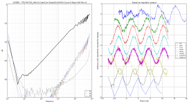
See attached PSRR measurement of TPS7A4700, it is similar to ADM7150... Note the measurement is inverted (it is a transmission measurement, Vout/Vin, so negative values in dB indicate high PSRR).
So, PSRR is crap and reaches zero above 100 kHz. Please don't show that to the designer of this otherwise excellent regulator, he may get a bit sad.
Why ???? Simple... Any regulator has got to have a voltage reference, which is somehow referenced to GND, so if there is noise on GND, it will appear on top of the reference also, and the regulator will happily add this noise to the output.
There are input capacitors on the 3-pin module... They're required for stability... Any noise on the input goes straight through the capacitors, and creates a current in the module GND pin, which lifts the regulator reference voltage, so the regulator's output will nicely track the input. Noise also couples from module GND into the output via the output capacitors.
This module is mostly a capacitor from input to output, with some DC regulation function at LF.
The output impedance is dominated by the pin Z.
I won't show the HF curves from the network analyzer, cause some of you may vomit. Just think what happens when you put some ceramic caps on a module, add > 10 nH pin inductance, and put more ceramic caps on the board. It's a complete mess of resonance & antiresonance spikes everywhere.
/BRICK FACEPALM
Somehow the TPS7A4700 EVM shows datasheet performance, ie excellent. This could have a relation to the fact the guys who did the layout know their stuff, the caps are placed with care in the right spot, the sense pins of the regulator are used for their purpose, and it is not a 3-pin module...
If you want 3 pins, just stick a damn LM317 !!!!!!! It will have higher performance than the fashionable superreg of the day with a crap implementation. If you want to use high performance, expensive chip like ADM7150, the implementation must be on par.
Or make a shunt reg... or any reg that doesn't have input caps ! Its output Z will still be dominated by the pins, but at least, if designed correctly, it will have PSRR.
Or do it the right way with a pinout like so : GND IN GND GND_SENSE GND OUT_SENSE GND OUT GND, plus another row of GND 'cause it's cheap.
Attachments
Last edited:
That is certainly better. Perhaps better still is discarding the idea of regulator-on-removable-daughterboard.... do it the right way with a pinout like so : GND IN GND GND_SENSE GND OUT_SENSE GND OUT GND, plus another row of GND 'cause it's cheap.
I don't have to. It is connected to ground through a resistor to the adjustment pin, forming a voltage divider with a resistor connected to the output.
If you attempt to measure the loop stability of an LM317 circuit, referencing IN and OUT to GROUND, you'll get the wrong answer.
Can someone please post a screenshot of the board so I can see for myself?
Analog has published a manual for the dev-kit -- with a graphic of their version of the board:
http://www.analog.com/static/imported-files/user_guides/UG-553.pdf
As can be seen in the simulations, the output Z of the ADM7150 is well under 1 milli-ohm up to 3KHz smoothly and rises to about 18 milli-ohms at 100KHz. The output Z is somewhat load dependent, especially below 1KHz, because the open loop gain of the LDO is load dependent.
I will have to get a development board from them and measure the phase-angle around the impedance dip. From this we can determine the best output cap for loop stability.
For the LA article I used Kelvin clips and probed around the circuit to find the lowest impedance point -- around 100Hz. You don't need an expensive analyzer to perform this test.
Just for reference, the LM317 measures about 3 milli-Ohms at 100Hz and the LT1963A around 10 milli-Ohms.
Hi all,
The designer of the ADM7150 was kind enough to run some simulations of the ADM7150 output impedance for several load cases. I've attached the simulations results to this response. As can be seen in the simulations, the output Z of the ADM7150 is well under 1 milli-ohm up to 3KHz smoothly and rises to about 18 milli-ohms at 100KHz. The output Z is somewhat load dependent, especially below 1KHz, because the open loop gain of the LDO is load dependent.
What capacitor was used in this sim ? Its ESR looks very high for a ceramic cap... maybe tantalum ?
As I just mentioned on another thread for low noise regulators, you're wasting your time using anything but the ADM7150 if noise is the spec you have to optimize. I just ran the device with a 50mA load and a 5uF bypass capacitor and come up with exactly the values shown on the datasheet.
I used the SOIC-8, and attached the device to an SOIC adapter using copper tape as the thermal pad.
The ADM7150 can be used as an adjustable regulator -- see the data sheet for the evaluation kit. I would imagine that you could use it for higher voltages by lifting the ground pin with a zener (not avalanche) diode, or using a pass transistor/mosfet such that the Vin/Vout limit isn't broached.
- Status
- Not open for further replies.
- Home
- Amplifiers
- Power Supplies
- Modern ultra low noise LDO - ADM7150