Have a look at the TO, there is a full schematic of the Naim!
The TO?
DOL, DOR and WCKO go straight through to the multiplexers. Looking at CLK there seems to be some sort gating logic possibly for stopped clock mode. There is also an option to ground the DOL, DOR and WCKO inputs via the multiplexers. Doesn't U33 just configure the PMD200 and then go to sleep ?
Oh BTW, I remembered that I checked the data sheet of SAA7324, and its IIS interface output format is the same as DIR9001 or AK4118. At the same time I tried all their formats. .
The only thing that is not sure is that SAA7324's main clock (MCLK) frequency in naim application is 16.9344MHZ or 11.2896MHZ?
Hi
Most lightly PMD200 could not accept I2S input format directly, without simple hardware interface. Like PMD100.
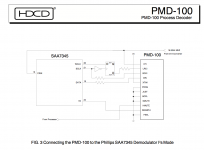
From PMD100 datas, example with SAA7345 I2S output format... The circuit adding "delay" for ONE bitclock to the LR latch line, maling MSBit with Latch.
Attachments
Last edited:
hi Zoran
Thank you, I checked the PMD200 (primary version Ver0.6) data sheet to show that it supports the IIS format. I once guessed that it does not support IIS, so I tried RJ, LJ, 16BIT, 24BIT and so on. The result tells me that there is no format that can correspond to it. Therefore, I focused on the input and output clock polarity to compare. Unfortunately, the timing diagram of the PMD200 data sheet is not clear, and I am not sure which mode is correct.
1. I used DIR9001+PMD200+AK4497 (single channel external filter mode) and it worked. The sound is very normal. But a strange phenomenon is that there is a certain chance that the MCU responsible for SPI will need to manually RESET and send data to PMD200 again to work normally, otherwise it will have problems with sound (improper register configuration). So I thought that I could solve the problem by sending data to PMD200 twice, so I used it to make the engineering version of PCM1702, the sound was normal, but it would still work if I manually reset the MCU or reset it multiple times.
2. Before I go to know JPK73, I cannot see the information that needs to send data multiple times from the data book. It is still a mystery to this day.
I'm fed up with the data sheet of the primary version of PMD200, it took me a lot of distances. I have suspected a few times that I had a problem.
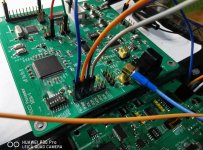
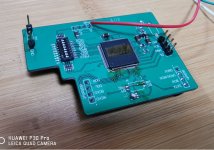
For the PMD200 chip information, I looked for PMD100 comparison (trying to find some commonalities through it), and I found almost all design works using PMD200 (including ARCAM CD92, TEAC D70, assmble D2.7, HDX2, SANLING CDT100, etc.). In the design works, their input interface is similar to CS8416, with direct DSP output.
For the PMD200 chip information, I looked for PMD100 comparison (trying to find some commonalities through it), and I found almost all design works using PMD200 (including ARCAM CD92, TEAC D70, assmble D2.7, HDX2, SANLING CDT100, etc.). In the design works, their input interface is similar to CS8416, with direct DSP output.
There is a place to draw key information: I use AK4118/DIR9001+PMD200+AK4497
If it is sent twice now to make PMD200 work, reset the DIR chip at this time, (AK4118/DIR9001) it will make PMD200 work abnormally, which behaves like high-frequency noise caused by asynchronous clock and data.
So one day I discovered that two official CD player service manual circuit designs were added to ASRC for asynchronous data input before PMD200. So I guess it must have encountered similar problems. Otherwise, why should ARSC be added to the PMD200 input front end?
Yes, it's a DS1054Z!
I can make the Arduino code repeat the reset of the PMD200 a couple of times, do you think this will help...?The SAA in the Naim is configured by a PIC, so I don't think we can figure out the output data mode by looking at the schematic... But if PCM1702 works well, PCM1704 should be the same! Maybe try to wire the left PCM1704 to DOR and the right to DOL to see if the chips are OK...?
And may I ask you: which CD-Player with PMD200 do you have? And which logic analyzer do you recommend?
--------------------------------------------------------------------
Hi friend ,I'm coming!🙂
1,RIGOL's DS series is great. worth having.🙂
2,I suggest to do the monitoring mode, wait for the system to reset the PMD200 3 times after power on, the length of each reset time is 300us~500us.
3,I confirmed that DOL and DOR have been exchanged, and the noise channel is DOR.
4,Currently I do not use the PMD200 commercial player, so the information I get can only come from the data sheet and service manual. The logic analyzer I used is a crowdfunding design by some hardware enthusiasts: DSLogic Plus, which is fast, but IO does not have isolation measures (Because IO isolation will reduce the speed of adoption) .URL:DSLogic Plus – DreamSourceLab
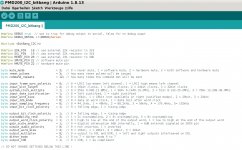
Here as promised the version with flexible settings:
Please check if everything is correct! The reset line is pulsed multiple times. Have a nice trip!
---------------------------------------------------------------------------------------
Wow, this version is so cleverly designed. If you don't consider the official data sheet, I think I can't find any flaws in this code.
I plan to compile and upload these codes tonight
Share the joy of success
-------------------------------------------------------------------------------
Excuse me,
sorry, please forgive me for answering this way. Because I was so excited, I suspected that life is wonderful because of this chip (PMD200) for more than a year.
I don't have a real thing, and I rely on this unreliable data sheet to stick to it. There are too many details to get along with this chip. I drew the engineering board PCB more than 6 times , Building AVR SPI code more than 20 times. Some were for pin errors, some were for changing the communication method, some were IO settings were wrong, and some were booting up sequence changes. In the end, I really had no choice. I used 2 PMD200s and tried to open the cover under the microscope to verify whether the chip is a real PMD200 (because it has been discontinued, and it has been for many years). I want to know whether the program has entered the PMD200? Why can I work for a while and not work for a while? I am going crazy.
it's good now. I met an amazing person and I called him JPK73 (forgive me for not knowing how to call him). Sorry for being a bit long-winded. Because it contains too many bitter stories. Countless tests. Countless debugging. Of course, I know very well that my cognition is very limited.These will seem very ridiculous in front of professional masters.
--------------------------------------------------------------------------------
Now solemnly announce that the code of JPK73 runs to make PMD200 run perfectly. Let me tell everyone that his code succeeded. He helped me get rid of PMD200 that made me painful.
-------------------------------------------------------------------------------
Thanks again to JPK73, and also to my enthusiastic friend: Zoran.
I admire you very much. Of course, your software is as admirable as you. it's great.
Because of you, make this project very meaningful.
If you need it, I will share all my test data and information.
-------------------------------------------------------------------------------
Excuse me,
sorry, please forgive me for answering this way. Because I was so excited, I suspected that life is wonderful because of this chip (PMD200) for more than a year.
I don't have a real thing, and I rely on this unreliable data sheet to stick to it. There are too many details to get along with this chip. I drew the engineering board PCB more than 6 times , Building AVR SPI code more than 20 times. Some were for pin errors, some were for changing the communication method, some were IO settings were wrong, and some were booting up sequence changes. In the end, I really had no choice. I used 2 PMD200s and tried to open the cover under the microscope to verify whether the chip is a real PMD200 (because it has been discontinued, and it has been for many years). I want to know whether the program has entered the PMD200? Why can I work for a while and not work for a while? I am going crazy.
it's good now. I met an amazing person and I called him JPK73 (forgive me for not knowing how to call him). Sorry for being a bit long-winded. Because it contains too many bitter stories. Countless tests. Countless debugging. Of course, I know very well that my cognition is very limited.These will seem very ridiculous in front of professional masters.
--------------------------------------------------------------------------------
Now solemnly announce that the code of JPK73 runs to make PMD200 run perfectly. Let me tell everyone that his code succeeded. He helped me get rid of PMD200 that made me painful.
-------------------------------------------------------------------------------
Thanks again to JPK73, and also to my enthusiastic friend: Zoran.
I admire you very much. Of course, your software is as admirable as you. it's great.
Because of you, make this project very meaningful.
If you need it, I will share all my test data and information.
Attachments
Last edited:
I am very happy that my code works now!!!
I added mute handling to the code: you can now let the code mute the PMD200 and specify the pins for software mute and hardware mute in the first section of the code:

The PMD200 will be muted during all programming activities such as changes of input rates, but muting can be completely disabled by setting mute_mode to zero.
Other possible settings:
@dqfan, your project is most amazing and impressive, well done! I am glad I could help, and I think you helped me also a lot, because I need to modify my Naim into a DAC when the transport becomes irrepairable sooner or later...
That's what I presumed, but I am not sure: I wonder if it polls pin5 to reset the PMD200 in special cases, or if it tracks pin2 to verify the signal condition...?Doesn't U33 just configure the PMD200 and then go to sleep ?
Can you please post the schematics of these players with PMD200? Maybe it helps...I discovered that two official CD player service manual circuit designs were added to ASRC for asynchronous data input before PMD200.
OK, I corrected the code to issue 3 resets with 1ms each and also included some other minor bug fixes, and corrections to the decsriptions of the settings, please see attched code. The data sheet is unclear about the output bit clock polarity: looking at table 5-7 (page 36) and table 7-1 (page 41) I don't know what is correct: 0 = falling edge and 1 = rising edge? Or 0 = rising edge and 1 = falling edge...???reset the PMD200 3 times after power on, the length of each reset time is 300us~500us.
I added mute handling to the code: you can now let the code mute the PMD200 and specify the pins for software mute and hardware mute in the first section of the code:
The PMD200 will be muted during all programming activities such as changes of input rates, but muting can be completely disabled by setting mute_mode to zero.
Other possible settings:
- if you set DEBUG to false in the first line no messages will be written to the serial monitor
- reset_pulses: set how many reset pulses you want after power on
- command_repeats: set how many times you want the commands to be sent to the PMD200
- etc. etc.
@dqfan, your project is most amazing and impressive, well done! I am glad I could help, and I think you helped me also a lot, because I need to modify my Naim into a DAC when the transport becomes irrepairable sooner or later...
Attachments
Last edited:
hi Zoran
Thank you, I checked the PMD200 (primary version Ver0.6) data sheet to show that it supports the IIS format. I once guessed that it does not support IIS, so I tried RJ, LJ, 16BIT, 24BIT and so on. The result tells me that there is no format that can correspond to it. Therefore, I focused on the input and output clock polarity to compare. Unfortunately, the timing diagram of the PMD200 data sheet is not clear, and I am not sure which mode is correct.
1. I used DIR9001+PMD200+AK4497 (single channel external filter mode) and it worked. The sound is very normal. But a strange phenomenon is that there is a certain chance that the MCU responsible for SPI will need to manually RESET and send data to PMD200 again to work normally, otherwise it will have problems with sound (improper register configuration). So I thought that I could solve the problem by sending data to PMD200 twice, so I used it to make the engineering version of PCM1702, the sound was normal, but it would still work if I manually reset the MCU or reset it multiple times.
2. Before I go to know JPK73, I cannot see the information that needs to send data multiple times from the data book. It is still a mystery to this day.
Hi. You done great job.
(BTW I did same I2S-to-LeftJust simple circuit for interface my discrete dac to I2S and it working realy good.)
.
I think that Master clock to the PMD200 should be present first. Before turn on PMD200 at power on reset. IF You feed PMD200 with external MCL from oscilator OR from other IC...
About sygnals If LRclk is inverted resulting in inverting channels, If data line is inverted will result in inverted phase At DAC analog out. But If the BCK (scK) OR/AND MCK are inverted could cause some damages to the sygnal?
.
Maybe to employ some galvanic isolation for programming registers lines?
something like this? Simply to disconnect other devices and "clocks" from digital ground and digital audio sygnals? I am not sure that is the right part just an notion...
Share the joy of success
-------------------------------------------------------------------------------
Excuse me,
sorry, please forgive me for answering this way. Because I was so excited, I suspected that life is wonderful because of this chip (PMD200) for more than a year.
I don't have a real thing, and I rely on this unreliable data sheet to stick to it. There are too many details to get along with this chip. I drew the engineering board PCB more than 6 times , Building AVR SPI code more than 20 times. Some were for pin errors, some were for changing the communication method, some were IO settings were wrong, and some were booting up sequence changes. In the end, I really had no choice. I used 2 PMD200s and tried to open the cover under the microscope to verify whether the chip is a real PMD200 (because it has been discontinued, and it has been for many years). I want to know whether the program has entered the PMD200? Why can I work for a while and not work for a while? I am going crazy.
it's good now. I met an amazing person and I called him JPK73 (forgive me for not knowing how to call him). Sorry for being a bit long-winded. Because it contains too many bitter stories. Countless tests. Countless debugging. Of course, I know very well that my cognition is very limited.These will seem very ridiculous in front of professional masters.
--------------------------------------------------------------------------------
Now solemnly announce that the code of JPK73 runs to make PMD200 run perfectly. Let me tell everyone that his code succeeded. He helped me get rid of PMD200 that made me painful.
-------------------------------------------------------------------------------
Thanks again to JPK73, and also to my enthusiastic friend: Zoran.
I admire you very much. Of course, your software is as admirable as you. it's great.
Because of you, make this project very meaningful.
If you need it, I will share all my test data and information.
Ohhh 🙂
I dint see this post - GREAT
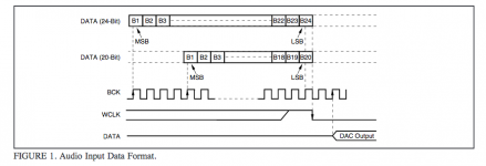
I checked again and again the data sheet, and the Naim (which has PCM1704s) clearly programs the PMD200 for WCPL=1, so how can that be if word clock output doesn't get inverted through the logic stage...? What do you think? Here is a diagram taken from the PMD100 data sheet, as far as I can see this is identical to the information I found in the data sheet of the PMD200:The output wordclock polarity is wrong. Conversion for the PCM1702 and the PCM1704 is triggered on the falling edge.
Yes, please send me all information you have!If you need it, I will share all my test data and information.
Attachments

PCM1704 has right justified format. Binary Two’s Complement.
Afer the LSB Word Clock (WCLK) should be falling edge. Also as BCK should be falling edge.
At the MSB BCK should be rising edge. For 20bit and 24bit data words.
(Page 7 audio data interface PDF, read “Stopped Clock” Operation chapter...)
Afer the LSB Word Clock (WCLK) should be falling edge. Also as BCK should be falling edge.
At the MSB BCK should be rising edge. For 20bit and 24bit data words.
(Page 7 audio data interface PDF, read “Stopped Clock” Operation chapter...)
Attachments
I am very happy that my code works now!!!That's what I presumed, but I am not sure: I wonder if it polls pin5 to reset the PMD200 in special cases, or if it tracks pin2 to verify the signal condition...?Can you please post the schematics of these players with PMD200? Maybe it helps...OK, I corrected the code to issue 3 resets with 1ms each and also included some other minor bug fixes, and corrections to the decsriptions of the settings, please see attched code. The data sheet is unclear about the output bit clock polarity: looking at table 5-7 (page 36) and table 7-1 (page 41) I don't know what is correct: 0 = falling edge and 1 = rising edge? Or 0 = rising edge and 1 = falling edge...???
I added mute handling to the code: you can now let the code mute the PMD200 and specify the pins for software mute and hardware mute in the first section of the code:
The PMD200 will be muted during all programming activities such as changes of input rates, but muting can be completely disabled by setting mute_mode to zero.
Other possible settings:
Question: I can improve the code to enable changes of settings on the fly so that you can type into the serial monitor for example "DITH#7" to activate dither mode 7. This is possible for all settings: so you can play with input settings, output settings, reset pulses, muting etc etc., I think this would be convinient for using the PMD200 for a DAC which also can handle other input rates such as 24bit / 96kHz...?
- if you set DEBUG to false in the first line no messages will be written to the serial monitor
- reset_pulses: set how many reset pulses you want after power on
- command_repeats: set how many times you want the commands to be sent to the PMD200
- etc. etc.
@dqfan, your project is most amazing and impressive, well done! I am glad I could help, and I think you helped me also a lot, because I need to modify my Naim into a DAC when the transport becomes irrepairable sooner or later...
--------------------------------------------------------------------------------------
hi friends
I recommend:
1. MCU enters sleep mode after sending data. (Need to analyze whether monitoring is needed)
2. Start resetting PMD200 after power-on. The reset logic is: first low level for 500us and then high level. 3 times.
3. I suggest adding the hardware mute function. The high level of pin17 HMUTE of PMD200 is mute, and the low level is played normally. The logic is: power on-reset-mute-send data completed-release mute. Because the process of sending data will cause the PMD200 to work abnormally and there will be a popping sound. (Of course, if I can make the reset function as a watchdog, I think it will be more perfect. If you put in too much effort, there is no need to try it)
4. I think the output pulse polarity problem can be determined according to the DA chip and DIR, because the PMD200 data sheet cannot understand the timing diagram (I spent a lot of time to verify its timing diagram), the most direct way is to try .
5. If the DAC output by PMD200 is PCM1702/04, and their working status is 8X mode LRCK=352/384KHZ mode, then PMD200 will not allow the input signal to be greater than 44.1KHZ, 16bit. Remember. If you want to input a signal greater than 44.1KHZ to PMD200, then you must run PMD200 at a reduced speed, such as 2X mode.
6. I don’t understand what DITH does? I found time to do verification tests.
7. Strict execution information: PMD200 xtal clock signal must be the highest priority, and it must be available before power-on reset. The main reason I use DIR9001 is that it has a low enough jitter, and more importantly, it does clock source switching.
8. I use a dedicated clock driver to drive the PMD200 output clock from CDCM7005, which can be isolated from the PMD to the clock circuit. Use ADI digital isolator to isolate the ground between DAC and PMD200.
Attachments
-
AKM4118+PMD200+ak4497_Project_6.pdf1.1 MB · Views: 144
-
pmd200HWSW-demo.pdf621.1 KB · Views: 130
-
classe_cdp-10_cd_playe_2002_sm.pdf967.6 KB · Views: 119
-
SHANLING_CD-T100_Tube_HDCD_Player_Schematic_Diagram.pdf348.9 KB · Views: 111
-
NAKAMICHI_dragon-cd-dac-ltd.pdf1.3 MB · Views: 119
-
 untitled.png105.4 KB · Views: 95
9. It is recommended to use DIR9001 or AK4118. When the SPDIF signal is not ready, most DIR chips will output some abnormal signals. For example, LRCK and SCK will work at some unstable frequencies, which will cause great interference to PMD200 at this time, a common phenomenon There are PMD200 information loss, register write failure, etc. However, DIR9001/AK4118 has no output (IIS interface signal) before the SPDIF signal is ready, while MCLK has an output (derived from an external clock).
10. The length of the PMD200 slot (important) should have been working normally during the explosion version of JPK73. Why is the sound abnormal? It is because the parameter of this register is incorrect. It is abnormal because the data obtained by reverse decoding is 24bit input and 32bit output.
11. I saw the serial monitoring screen from the last version of the software. The input register has been sent continuously more than 10 times before it can be sent successfully. I still can’t explain why?
- Home
- Source & Line
- Digital Source
- mod NAIM CD-player with PMD-200 into stand alone DAC