I attached a file with links to bootloader HEX files: please extract the HTML file from the ZIP and open it in the web browser. Or you can access it as follows: open this link, scroll down, click on the link "How to reflash Atmel bootloader - (local)", and you will find the HEX files!
Attachments
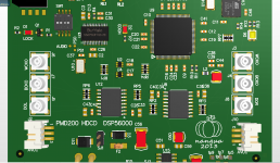
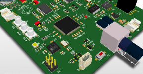
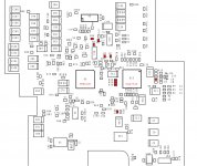
It took 2 days to complete the basic construction of the framework: DIR9001+PMD200+digital isolator. Now add ST fiber and balanced SPDIF signal.
future:
1. It distributes the left and right channel signals to the LR channel PCM1704 DA analog board respectively.
2. Use 18650 lithium battery pack to form positive 16.8V and negative 16.8V. When charging, the dual power supply is automatically changed into a single power supply, and when working, the two single power supplies are connected in series to become a dual power supply for use by the LPF circuit.
Thanks for the contribution of JPK73, so that this project can continue
Attachments

2 days?!?!? You are very fast!!!! I will try to work out a daughter board for the CDS3 which makes it possible to use the Naim as a CD player and as a DAC with external digital input, as non invasive as possible. I hope I may ask for your help as soon as I am ready with some kind of basic concept...!
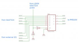
This is good, there is no problem, I think the external I2S signal can not go too long. I recommend using RG176 shielded cable for I2S signal transmission.
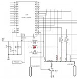
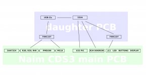
Looking at the schematics of the Naim CDS3 I realise that I can't use LDON (at R8) for switching between DAC mode and CD-player mode... So I looked into using the door switch, here are simplified diagrams:

The door switch supplies VDD to the VAM1250 disc drive, so I can't just pull out the connector and re-route it through my (future) daughter PCB. Instead I have to use the DOORSW line:

I plan to take out R34 and connect the 2 pads to my MCU:

Same I can do with the i2s lines (R38~R40). The clock track I have to cut somewhere between R54/U43/U47/U48/U57 and inject the clock signal from the USB board there.
My plan is to send a "door open" signal during DAC mode from my Arduino (or other MCU) to the PIC so that the CD-player is locked from being used. As soon as I switch back to CD-player mode the door switch can be read by the PIC again. Please have a look at this crude circuit simulation I made: click on the "door switch" to open and close the door, and click on the other switch labelled "Arduino" which simulates an output pin. The circuit with the two transistors is taken from the Naim schematic shown in the first picture of this post.
What do you think??
The door switch supplies VDD to the VAM1250 disc drive, so I can't just pull out the connector and re-route it through my (future) daughter PCB. Instead I have to use the DOORSW line:
I plan to take out R34 and connect the 2 pads to my MCU:
Same I can do with the i2s lines (R38~R40). The clock track I have to cut somewhere between R54/U43/U47/U48/U57 and inject the clock signal from the USB board there.
My plan is to send a "door open" signal during DAC mode from my Arduino (or other MCU) to the PIC so that the CD-player is locked from being used. As soon as I switch back to CD-player mode the door switch can be read by the PIC again. Please have a look at this crude circuit simulation I made: click on the "door switch" to open and close the door, and click on the other switch labelled "Arduino" which simulates an output pin. The circuit with the two transistors is taken from the Naim schematic shown in the first picture of this post.
What do you think??
Attachments
DOORSW is an input judgment signal, it cannot make an output judgment, and its judgment condition is also related to HOMESW. Therefore, I personally recommend not to use DOORSW signals. Use the MOTOR2 signal (spindle motor) to receive the judgment logic of the spindle motor signal, because the spindle motor only rotates a few times when there is no disc. This can be completely blocked by the arduino. If you don't use the turntable, just don't put the disc, then play The device will not start. This is when ARDUINO controls the DAC to work independently. When there is a disc player playing, the spindle motor is activated to switch to the player mode, It can also reduce the installation of a switch button on the panel..
The approximate working logic of the spindle motor is:
1. When detecting a disc: rotate a few times and then stop.
2. When there is no disc: it will stop permanently after a few revolutions, until the signals such as doorsw and homesw are ready.
3. When there is a disc: rotate until the playback is complete and stop.
1. When detecting a disc: rotate a few times and then stop.
2. When there is no disc: it will stop permanently after a few revolutions, until the signals such as doorsw and homesw are ready.
3. When there is a disc: rotate until the playback is complete and stop.
DOORSW is an input judgment signal, it cannot make an output judgment
I plan to feed DOORSW to the 32U4 and generate the output signal with the 32U4 for the PIC 😎
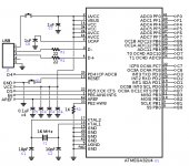
Thank you! Here is my plan how to switch the Naim between external DAC mode and internal CD-player mode:
Coud be maybe better to use single IC per line? Because of the different F presented in the small DIE inside the Quad chip? And also one decoupling cap for 4 segments inside chip...
Iwill go there for 4 x single IC. It will be minimal space additionaly but it coud be less ground bounce, less interaction among the lines 🙂
Thanks, I will consider single HC157s for the important signals. Is there any better IC I could use for that?
Maybe some from the IC series to match logic levels of PMD200?
Same value of power supply, SMD package (technology level).
Sorry is the +3.3V value for the power supplu for the PMD200?
some datas for the PMD200 inputs logic levels hi/lo could be of help.
AND
for the adjust signal integrity put place for the resistors each input and each output at the "selector" IC? These drivers can employ up to 15-16 next inputs, so they cpable to drive 15X classic capcitance logic inputs. Butthay will drive just one on the PMD. Put the trimmer pot in the resistor place and adjust for minimum ringing on the scope? Inputs At the IC first to adjust. Because of the different F values will be sligh different. But larger than classic 22ohms. Ecpect up to 100-120ohms. 🙂 After setting up each value put in the place resistor. I suggest melf type, but any type will be good, near measured value.
I found some datas about input values seems like lo=0.3/0.4V hi=2.4V
"The specifications in the AC electrical characteristics section are derived from specifications provided in the Motorola DSP56364 Technical Datasheet (DSP56364/D Rev 1). Timing waveforms are tested with a VIL maximum of 0.3V and a VIH minimum of 2.4V for all pins except EXTAL, which is tested using the input levels shown in Note 8 of the previous table. AC timing specifications, which are referenced to a device input signal, are measured in production with respect to the 50% point of the respective input signal’s transition. Output levels are measured with the production test machine VOL and VOH reference levels set at 0.4V and 2.4V respectively."
.
"6. VCC=3.3V +- 0.16V"
.
I read something that could be related with "3 x reset" issue:
maybe the PMD200 does not recognize fast enough software mode? Maybe IC assuming that is in hardware mode for some little period of checking after 1st reset operation mode pin?
.
CONTROL INTERFACE
Hardware mode is selected by tying PROG LOW. The PMD200 checks this signal as it comes out of reset. This enables the Hardware-mode-only control pins DITH, OSIZ0, OSIZ1, /COB, JUST, BCPL, FSEL, and SCAL.
NOTE: These pins are not 5V tolerant.
I took a quick look at the
3.3V single non-inverting buffer/line driver with 3-state output
74HC1G126
74LVC1G125
and other types probably
3.3V single non-inverting buffer/line driver with 3-state output
74HC1G126
74LVC1G125
and other types probably
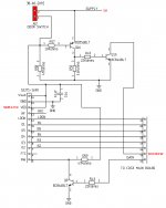
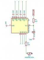
Some lines are at 5V, some at 3.3V, and some at 3.14V. The PMD is powered with 3.14V as is the small PIC (U33). The SAA is at 3.3V, and the larger PIC at 5V. The HCT125 will be good for sending out 5V signals from the 32U4. Here a basic example of how I intend to manipulate the DOORSW signal by desoldering R34 and connecting my circuit to there:
Attachments
Last edited:
- Home
- Source & Line
- Digital Source
- mod NAIM CD-player with PMD-200 into stand alone DAC