Sorry, I didn't make my question clear... I try again:

Do I have to take the clock signal for the reclock flip flops from point "A" or from piont "B"...?
I want to read LRCK with my micro controller for sample rate detection: do I have to read LRCK at point "C" or "D"...?
Do I have to take the clock signal for the reclock flip flops from point "A" or from piont "B"...?
I want to read LRCK with my micro controller for sample rate detection: do I have to read LRCK at point "C" or "D"...?
Attachments
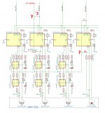
Hi does not matter a lot. You can use D&B or C&A.
.
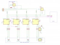
What source do You connect from 2A inputs of the '125 selector ic-s?
External USB/I2S source or Naim?
.
Did You check pin 26 @ SAA ic with the scope to measure the MCK out if exists?
.
What source do You connect from 2A inputs of the '125 selector ic-s?
External USB/I2S source or Naim?
.
Did You check pin 26 @ SAA ic with the scope to measure the MCK out if exists?
What source do You connect from 2A inputs of the '125 selector ic-s?
External USB/I2S source or Naim?
2A = external i2s (AK4118 or USB)
1A = Naim (SAA)
Did You check pin 26 @ SAA ic with the scope to measure the MCK out if exists?
Not yet, but I will add an inverter if MCLK is out of phase!
"Not yet, but I will add an inverter if MCLK is out of phase!"
This pin is unconnected / unused in Your SCH
"2A = external i2s (AK4118 or USB)
1A = Naim (SAA)"
So You plan to leave Naim I2S outs without reckloker, and only recklock external I2S source?
This pin is unconnected / unused in Your SCH
"2A = external i2s (AK4118 or USB)
1A = Naim (SAA)"
So You plan to leave Naim I2S outs without reckloker, and only recklock external I2S source?
From external USB/I2S interface You will have alrady "matched" MCK with respect to 44/48 base. So You dont need selector for this. And if You only recklock external I2S source, simple use external MCK already present at the output.
Last edited:
So You plan to leave Naim I2S outs without reckloker, and only recklock external I2S source?
Yes!
From external USB/I2S interface You will have alrady "matched" MCK with respect to 44/48 base. So You dont need selector for this.
But I need to inject the external MCK from USB/I2S to the PMD200, right?
This pin is unconnected / unused in Your SCH
MCK at 1A of i2s-switch IC is not from SAA but from Naim clock. MCK at 2A is from USB or SPDIF receiver IC.
I don't want to reclock Naim i2s because I want to keep it as original as possible.
Last edited:
Sorry , excuse me!
My personal opinion is that even if the LRCK frequency needs to be detected, MCLK is not used. No need for Re-clock .
Detecting the LRCK frequency with the MCU is like probing the LRCK pin with an oscilloscope. In the same way, the reading tells us the sampling frequency received by the DIR device.
So why should we pay attention to MCLK (Master Clock)?
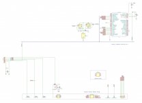
Please see the picture, it can detect。
My personal opinion is that even if the LRCK frequency needs to be detected, MCLK is not used. No need for Re-clock .
Detecting the LRCK frequency with the MCU is like probing the LRCK pin with an oscilloscope. In the same way, the reading tells us the sampling frequency received by the DIR device.
So why should we pay attention to MCLK (Master Clock)?
Please see the picture, it can detect。
Attachments
Many thanks, dqfan and Zoran! I draw my schematic with your suggestions:

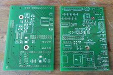
I checked the PCB: it's not possible to cut the track of MCLK, instead I have to desolder U43 and inject MCLK there:
I checked the PCB: it's not possible to cut the track of MCLK, instead I have to desolder U43 and inject MCLK there:
Attachments
Last edited:
The master-clock signal entering PMD200 is through 47ohm resistor R53. Remove it and use the same method as WCLK to switch. No need to cut PCB traces.
Last edited:
The master-clock signal entering PMD200 is through 47ohm resistor R53. Remove it and use the same method as WCLK to switch. No need to cut PCB traces.
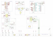
If I use R53 to inject MCLK: what happens to the logic ICs which receive MCLK? For example U48, U6 etc.:
Attachments
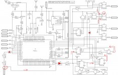
Before removing R53, can you tell me what the EXTAL frequency is now? 16.9344Mhz?or 11.2896Mhz? What is the 4pin output frequency of U6?
3Q
3Q
Last edited:
But I need to inject the external MCK from USB/I2S to the PMD200, right?
yes You need external MCK for recklock external I2S.
And You ususaly already have information about Fs In combinations of some output pins at the USB/I2S interface.
Bare in mind that If You plan to use longer cables for external I2S source, probably You will have to transfer signals balanced transmitter / receiver.
Last edited:
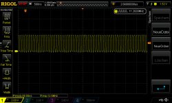
Somebody chesk with csope pin 26 of SAA chip? Preferably with SCK out line on second scope channel?
To determine what is the F of this MCK out and rise/fall with respect to SCK
To determine what is the F of this MCK out and rise/fall with respect to SCK
Somebody chesk with csope pin 26 of SAA chip? Preferably with SCK out line on second scope channel?
To determine what is the F of this MCK out and rise/fall with respect to SCK
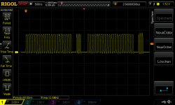
I checked with scope, see attached screen shots. The frequencies are:
LE PCM1704 (@ U8 pin4): 352.9kHz
XTAL PMD200 (@ R53): 16.9392MHz
So it seems Naim uses the logic stage to generate stop clock condition for the PCM1704 DAC chips as mentioned in the datasheet.
Attachments
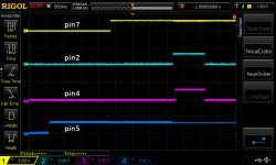
Small progress: trying to understand the logic circuit behind pin2/4 of U33. Here are 2 simulations: this one shows that pin2 could be used to disable the output of U51, but this also could have been done in the firmware of U33. This one shows that the circuit seems to work as a watchdog: pin4 of U33 detects if WCKO is out of sync or missing to be able to re-program the PMD200... Any advice?
With the great help (again!!!) by dqfan that circuit finally seems to be decoded:
PIC (U33) watchdog for output detection of WCKO from PMD200:
- after power up pin2@U33 goes high to activate watchdog circuit
- pin4@U33 goes high if WCKO is detected
- after WCKO is confirmed pin2@U33 goes low
- after that watchdog circuit is inactive
Simulation: click here
PIC (U33) watchdog for output detection of WCKO from PMD200:
- after power up pin2@U33 goes high to activate watchdog circuit
- pin4@U33 goes high if WCKO is detected
- after WCKO is confirmed pin2@U33 goes low
- after that watchdog circuit is inactive
Simulation: click here
Attachments
Last edited:
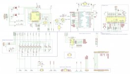
I decided to ditch the CD-player mode, the DAC-only mode is enough complicated. Attached the revised schematic: spdif simplified, switching between usb and spdif now with single gate LVC125s, alternative mcu (modul or directly soldered to PCB), divider for frequency detection, and other minor changes...
Attachments

- Home
- Source & Line
- Digital Source
- mod NAIM CD-player with PMD-200 into stand alone DAC