In loop() the repeated commands might be too fast, try this code:
BTW do you prefer to have three hex codes or one 24bit binary string in the Arduino sketch?
Code:
#include <SPI.h>
#define CS 10  // chip select pin
SPISettings settings(1000000, MSBFIRST, SPI_MODE1);

void setup() {
  delay(3000);
  pinMode(CS, OUTPUT);
  digitalWrite(CS, HIGH);
  SPI.begin();
  delay(1);
  for (int i = 0; i <= 12; i++) {
    spi_transfer(0b000000000000100110000001); // 0x00, 0x09, 0x81
    spi_transfer(0b000100000001111101100101); // 0x10, 0x1f, 0x65
    spi_transfer(0b001000000000000000000000); // 0x20, 0x22, 0x23
    delayMicroseconds(100);
  }
}

void spi_transfer(uint32_t value) {
  byte buf[3];
  buf[0] = (value >> 16) & 0xFF;
  buf[1] = (value >> 8) & 0xFF;
  buf[2] = value & 0xFF;
  digitalWrite(CS, LOW);
  SPI.beginTransaction(settings);
  SPI.transfer(buf, sizeof buf);
  SPI.endTransaction();
  digitalWrite(CS, HIGH);
  delayMicroseconds(100);
}

void loop() {}
Last edited:
According to the information read by the PIC MCU, the input can be determined:
Input Reg🙁0x00, 0x09, 0x81 ) = 24BIT,384XFS,I2S,44.1Khz ,right-justified.
Output Reg🙁 0x10, 0x1f, 0x65)= 32Bit, 8X, IIS format.
Input Reg🙁0x00, 0x09, 0x81 ) = 24BIT,384XFS,I2S,44.1Khz ,right-justified.
Output Reg🙁 0x10, 0x1f, 0x65)= 32Bit, 8X, IIS format.
hi
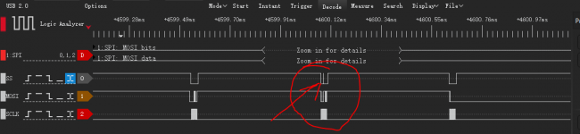
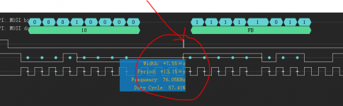
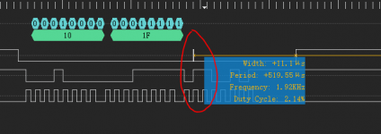
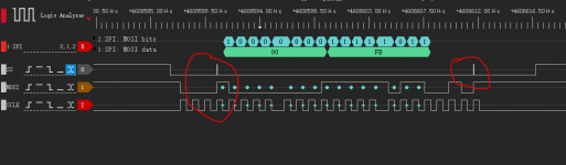
Today I ran this code, and accidentally discovered that a pulse with a width of +50ns appeared randomly in SS. It appears randomly, causing the register to receive incorrect configuration data sometimes, so it does not work. My screenshot is attached, hope to help me analyze it when you are free. thank you very much.
Use the code
-
-----------------------------------------------------------------------------------
#include <SPI.h>
#define CS 10 // chip select pin
SPISettings settings(1000000, MSBFIRST, SPI_MODE1);
void setup() {
delay(3000);
pinMode(CS, OUTPUT);
digitalWrite(CS, HIGH);
SPI.begin();
delay(1);
for (int i = 0; i <= 12; i++) {
spi_transfer(0b000000000000100110000001); // 0x00, 0x09, 0x81
spi_transfer(0b000100000001111101100101); // 0x10, 0x1f, 0x65
spi_transfer(0b001000000000000000000000); // 0x20, 0x22, 0x23
delayMicroseconds(100);
}
}
void spi_transfer(uint32_t value) {
byte buf[3];
buf[0] = (value >> 16) & 0xFF;
buf[1] = (value >> 8) & 0xFF;
buf[2] = value & 0xFF;
digitalWrite(CS, LOW);
SPI.beginTransaction(settings);
SPI.transfer(buf, sizeof buf);
SPI.endTransaction();
digitalWrite(CS, HIGH);
delayMicroseconds(100);
}
void loop() {}
Attachments

OK, can you send me your Excel file with the table you made? I will program that into the code so that we can change all settings easily!
Last edited:
Thanks! I think there is a problem with the third sequence of 0x20, 0x22, 0x23: this writes to a reserved bit, better to try 0x20, 0x00, 0x00! Other than that: great work, many thanks!!!
As for the spikes on the chip select line: most likely an RF issue. Make all wires short (max 5 inches), and make sure ground is well connected. Also make sure the PMD200 is 5V tolerant as the UNO outputs HIGH as 5V - in the Naim it was 3.3V...
As for the spikes on the chip select line: most likely an RF issue. Make all wires short (max 5 inches), and make sure ground is well connected. Also make sure the PMD200 is 5V tolerant as the UNO outputs HIGH as 5V - in the Naim it was 3.3V...
Last edited:
Thank you, the third register is as you said, the actual written value is 0x20,0x00,0x00.
Spike problem: The SPI signal line is about 10CM long for the temporary Dupont line. What's interesting is that I accidentally removed the USB line and disconnected the PC from the UNO. The spikes were a lot less, but it still exists. So I am planning to modify the cable to increase the shielding performance.
thanks for your suggestions.
Last edited:
Wise,
I plan to buy a USB isolator, which can reduce a lot of debugging troubles. Now PMD200 is working, but the sound is broken like the data format is incorrect. I plan to redesign the PCB to test and see if I can find the problem.
Thank you friend again, thank you for your great support, your outstanding programming skills make me admire me.
Last edited:
If the PMD200 outputs a signal with distortion I would not start to redesign the PCB: I think the programming still is not right. Also I would recommend to go with I2C as we know that it can work. Here is an I2C code with a speed of 12.5kHz and additional output to the serial monitor, please check:
Code:
#include <Wire.h>
void setup() {
delay(2000);
Wire.begin();
// speed of 12.5kHz for Arduino UNO, see [URL="http://www.gammon.com.au/i2c:"]www.gammon.com.au/i2c[/URL]
TWBR = 158;
TWSR |= bit (TWPS0);
Serial.begin(115200);
delay(1000);
for (int i = 0; i <= 12; i++) {
i2c_transfer(0b000000000000100110000001); // 0x00, 0x09, 0x81
i2c_transfer(0b000100000001111101100101); // 0x10, 0x1f, 0x65
i2c_transfer(0b001000000000000000000000); // 0x20, 0x00, 0x00
delay(3);
}
}
void i2c_transfer(uint32_t value) {
byte buf[3];
buf[0] = (value >> 16) & 0xFF;
buf[1] = (value >> 8) & 0xFF;
buf[2] = value & 0xFF;
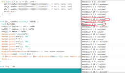
Serial.print("sending: ");
Serial.print(buf[0], HEX);
Serial.print(" ");
Serial.print(buf[1], HEX);
Serial.print(" ");
Serial.print(buf[2], HEX);
Serial.print(" ");
Wire.beginTransmission(0b0000000); // 7bit slave address
Wire.write(buf, sizeof buf);
if (Wire.endTransmission()) {Serial.println("error!");} else {Serial.println("success!");}
delay(1);
}
void loop() {}
Last edited:
I really admire your pragmatic spirit in the face of problems, and your suggestions are very good. When I reviewed the entire design process today, I also found that the I2C problem was not solved, and I still need to study it. Therefore, I will test the I2C control over a period of time.
Thanks again
Thanks again
Welcome! Just to make sure: the above example will (only) work on the Arduino UNO: if you use an attiny, teensy, or ARM, the speed setting will not work. The slave address needs to be set as binary 7bit (as shown in above example), GND needs to be connected between the UNO and the PMD, and the i2c speed is set to the registers of the UNO and will generate other speeds on other MCUs. I will make a bitbang version as well so that we can see if that works better. Please post analyer screen shots of the i2c code shown above so that I can trouble shoot it!
Last edited:
Very strange, I thought I had ignored pmd200, pin24=MOSI/HA0 and pin23 HA2 needs to be low, but I didn’t do it, so I2C can’t be searched. So now I have set them to low level, but still can’t search. I2C slave address, so I uploaded the I2C you wrote to try to communicate with PMD200, and I saw the attachment information in the serial monitor. Could you please help me analyze what else is there?
Ok, please post the serial monitor output and the logic analyzer screen shots so that I can see what happens! PMD200 can't be detected with the slave address search script I guess...
----------------------------------------------------------------------------------
TKS
Could you post a schematic of the analog circuitry after the PCM1704s?
Have a look at the TO, there is a full schematic of the Naim!
The ouptput of the serial monitor looks good!!!!!!!!!!! Very similar to the output of my Naim which also had a lot of NACK replies from the PMD:
The ouptput of the serial monitor looks good!!!!!!!!!!! Very similar to the output of my Naim which also had a lot of NACK replies from the PMD:
Attachments

Last edited:
- Home
- Source & Line
- Digital Source
- mod NAIM CD-player with PMD-200 into stand alone DAC