Thanks for the reply, X. So, my idea is not so absurd? The 4FE35 (and neo magnet 4FE32) is available in 16 Ohms as well. I'd rather stick with 8 Ohm total speakers.
And lastly, when you say "The sims actually are more perfectly suited for the dual 4FE35's". Is that for 0.53 size?
It's interesting that you say that. I think it would aesthetically be better to have the bigger driver at the bottom position to follow the K-aperture shape. But looks come second I suppose. I really find the highs quite adequate. It's the lower frequencies that I want to boost. Would the 4" driver work equally well in both positions?You will want to put the smaller one at the bottom position to give more highs, and the larger one on top.
And lastly, when you say "The sims actually are more perfectly suited for the dual 4FE35's". Is that for 0.53 size?
Last edited:
I was remembering the sim incorrectly - it was the dual TC9FD that is more ideal for 0.53x than dual 3FE25. For the 4FE35, you need to expand the length and depth to 0.60x scale and reduce width to 0.47x scale. The 16ohm ones cannot be made to work well unfortunately, the Qts is just too high and you get a large bass overshoot. It may sound ok, but not ideal. The other option is to run dual 4ohms in series. I will have to simulate that though before you try to build it. I am away from my simulation computer at the moment as I am on travel. Give me a few days and I will take a look at how to get an 8ohm nominal dual 4FE32-4ohm in series for 8ohms nominal. It will probably be a wash on sensitivity though.
For us tube guys, how do you think two 8 ohm drivers in series would perform? I'm considering different options for 16 ohm speakers for those that may wish to build my Flea amplifier design so that there is a bit lighter load/higher impedance on the output transformer, and dual TC9FD18-08, 3FE25-8 or 4FE25-8 would be handy, as they could be wired for both 4 or 16 ohms for different applications.
Dual 8 ohm drivers in series would cut the sensitivity down because 1/2 the current flows for same voltage. So you may have twice the cone area, the current is only half so overall sensitivity remains the same. This may be enough for you if looking for a 16ohm driver.
I have to run a simulation but it doubles the inductance. It may reduce frequency response if native inductance of the voice coil it high.
I'm just preparing to build a pair of 0.4x with Faital Pro 3FE25s (4 ohm), driven by a home-made stereo spud amp. The OTs expect 6ohm so a slight mismatch, but whatever... I've the practically everything ready - scale templates printed out, magic foam sponges, stuck on felt etc etc.
A quick check - referring to MuddJester's fabulous plans - should the 'side' panels also have foam applied?
A quick check - referring to MuddJester's fabulous plans - should the 'side' panels also have foam applied?
Internally apply the foam to the side panels as well. Basically any surface with a line of sight to the back of the driver should have foam or felt in it. The 3FE25-4 is a great driver. Add a 1ohm 2w (or more) metal thin film series resistor if you want to get closer to 6ohms. It’s only a very slight loss of sensitivity but may make it safer for your amp.
The 3FE25-4 is a great driver. Add a 1ohm 2w (or more) metal thin film series resistor if you want to get closer to 6ohms. It’s only a very slight loss of sensitivity but may make it safer for your amp.
Or use the 8 Ohm version.
Or use the 8 Ohm version.
+1
Not that going for 4 ohm would hurt anything, it will increase power slightly (but not noticeably) at a smidge higher distortion when compared to a 6 or 8 ohm load. Plate shunt feedback as discussed will help drive the lower impedance, so I wouldn't worry too much.
Thanks all. I'll give the 4 ohm a shot initially. Any problems and I can always do as X or Skylar suggest. Will be glad to have these projects "finished"!
My technique will be to
- trace out the templates I've made (print outs on A3 paper) on to the foam board
- cut along the inside of the lines, and
- hot glue everything but the final side & front together.
Then
- Stick on foam / felt / cushion material,
- wire up, and
- seal side & front with PVA.
I'll use little bits of balsa wood to help the speaker screws bite in.
Conscious of want a seal throughout I'll try and be methodical and slow. I've enough foam board for a 3rd unit in case I make a real hash of it!
hey X - since there's a "RGB" craze, perhaps one could light the front chamber (or entire foam core build) of a K - even a color organ type
https://youtu.be/pmCLFYc9J1I
https://youtu.be/pmCLFYc9J1I
So I've got all the pieces cut, the foam and felt ready to go, guides marked out on the sides to help in glueing.
However, when I attempted to make the first bend (folding towards the score) it really wasn't easy to get to 90deg, and eventually it ripped. So, before cutting a new part I experimented with the scoring - I've ended up making v-shaped (or as close to V as I could) scores so the fold puts the outer bend under less tension.
Has anyone else done this?
Also, when glueing, is it better to:
- glue (hot) along the edge of the foam and stick down (will the glue remain sticky for long enough to do the long edges?)
- tack with hot glue at various points to get it in place, then fill in along the 90deg edge to make the seal?
- some other method?
T
However, when I attempted to make the first bend (folding towards the score) it really wasn't easy to get to 90deg, and eventually it ripped. So, before cutting a new part I experimented with the scoring - I've ended up making v-shaped (or as close to V as I could) scores so the fold puts the outer bend under less tension.
Has anyone else done this?
Hi Tristan
You're probably not using paper clad foam board. If you're using Depron or similar foam board without the paper sides, then V-grooves should work fine, as you've discovered.
The glue should stay sticky long enough to put the long edges in position, unless your ambient temperature is very low. In that case, clear epoxy would work better, I think.
Thanks Skylar, I think I've the normal stuff - attached is a picture of one of the rips. It certainly feels like glossy photo paper, but thinner. I'll pre-fold each joint and if I get another rip I can always re-make the piece, but hopefully no need with v-scores.
And I think I'll test the hot glue inside on a spare piece for timing. I had planned to use white PVA afterwards on the joins to seal, so will continue with that unless the hot glue is so easy that I can just go over each edge.
And I think I'll test the hot glue inside on a spare piece for timing. I had planned to use white PVA afterwards on the joins to seal, so will continue with that unless the hot glue is so easy that I can just go over each edge.
Attachments
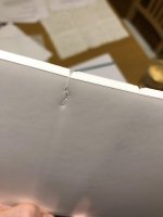
Thanks Skylar, I think I've the normal stuff - attached is a picture of one of the rips. It certainly feels like glossy photo paper, but thinner.
I agree, that looks like the normal stuff. But maybe it's a denser foam than what most guys use. Mine made a very nice, smooth bend after cutting through the paper on the inside of the bend.
If you have a thin metal ruler try pressing it down into the bend before you start the bend, it can help pre-crease it to keep it from breaking... try it on some scrap first of course!
If you have a thin metal ruler try pressing it down into the bend before you start the bend, it can help pre-crease it to keep it from breaking... try it on some scrap first of course!
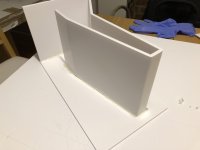
That’s a good idea. Will do for the next attempt. I have a gluey mess - in the time it took for me to apply to the long edge, lift, rotate and place, parts had dried a bit meaning there are tiny gaps. So I plastered the edges with more!
Will need to trim a bit off the lower front edges where there’s a bit of an overhang - to allow the front to mate properly.
Attachments
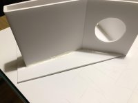
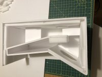
Almost there...
Have had a bit of trouble with glueing the back piece on, so my aesthetics aren’t as living room friendly as I’d hoped. Will also need to go over a few of the outer joins with PVA or UHU glue to ensure there’s a seal.
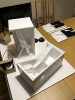
Not sure how dense the stuffing should be? Difficult one to describe, but I teased it apart a bit before putting it in, so it is less dense than in the packet.
Hoping to finish them off tomorrow and finally hear them along with my new amp!
Have had a bit of trouble with glueing the back piece on, so my aesthetics aren’t as living room friendly as I’d hoped. Will also need to go over a few of the outer joins with PVA or UHU glue to ensure there’s a seal.
Not sure how dense the stuffing should be? Difficult one to describe, but I teased it apart a bit before putting it in, so it is less dense than in the packet.
Hoping to finish them off tomorrow and finally hear them along with my new amp!
Attachments

- Home
- Loudspeakers
- Full Range
- Mini Karlsonator (0.53X) with Dual TC9FDs