FYI/FWIW, the pioneer's way to get 'close enough' acoustic phasing without measurement is to vertically align the VCs and reverse phase the HF to account for the XO's delay; otherwise you have to add the XO's number of degrees of offset to physically 'march' the HF backwards in time to wire both positive phase.

I physically time aligned (apart from tapped horns), back in the day when I was using passive x/o's.
Vertically aligned you end up with a dish effect.
Sounded better for it.

Also remember phase switch for the midbass and upper mid horn pairs (every other driver pair going up).
Worked pretty well.
Vertically aligned you end up with a dish effect.
Sounded better for it.
Also remember phase switch for the midbass and upper mid horn pairs (every other driver pair going up).
Worked pretty well.
@Speedysteve7 that is a nice drawing and the way to go when you cannot use dsp. But my point is that the way the horn mouths in your drawing are placed in space means different reflection points for each mouth and that is less optimal in my experience. Dsp allows you to align the horn mouths in such a way that the reflection bounce fom the back and side walls is congruent.
I get it, this makes sense to me but not sure it is a time alignment issue.around the crossover frequency, where both horns play the same frequencies, the mid/high horn mouth in the corner has a very short distance to the back wall, while the midbass horn mouth has a larger distance to the back wall. So the reflections from the back wall are messed up (that is my theory anyway). With back wall, I mean the wall behind the speakers. There is also a back wall behind your back, the same applies there.
Yes^^ I can understand it changed the reflections of the room by moving the speakers to a different distance from the wall. The direct vs reflected sound resulted in a negative way. When I said there wasn't much audible difference between physical vs DSP alignment, in both cases it was assumed the crossover frequency was dialed in correctly (using measurements, test tones, etc.) In my scenario, the midbass remained in the same spot, therefore we experienced much different results. For me, going through this method by ear gets it close but measurements provide that last bit of precision the ears can't quite pick up. We're talking micro seconds of detail which could be the difference between a small peak or dip, or flat response near crossover point. As you described, "the horns to play with one voice and make them disappear." I do not have the ability to do that by ear alone without measurements.the room is part of the system, ultimately.
Yes, tuning by ear will take you far, but it is always a good idea to check using measurements 👍
Depends IME; assuming a HIFI/HT app, combine a male, female with youthful hearing yields at most the difference between closest to life-like Vs a (relatively) sterile recording.
Is there an "industry" standard for radiation angle ... half space, free space?
Horn lower cutoff.
1) Earlier in the thread Norman Bates noted DJK's recommendation "bass horn needs to be half wavelength lower than the mouth".
2) Also read, Fc = Fx / 1.25
3) And specifically to FLH with vent - for midbass, tune the chamber to approx one octave below the horn's Flc.
1 & 2 are based on what type of horns ?
Regarding 3, didn't Altec A7 and JBL 4560A tune about two octaves lower?
Half space is easy because that’s what straight baffles look like, but it doesn’t necessarily fit in with the shape of a listening space. Some people look beyond that and just consider the overall amount, but those that look at the potential for individual reflections may see more benefit in quarter.
We were at a gig on Wednesday.
Small to medium theatre venue.
Sound reinforcement, no tapped horns though🙂
Treble was a bit harsh, mid bass to bass was a bit muddy. Down to 40Hz.
Gobs of kick and relentless punch though.
Okay for live, your eyes see and your brain fills lots in, I think.
Next evening at home we moved the seating position from about 10ft away from the mid bass horns to over 13ft.
Toed the horns out accordingly and re-time aligned.
Def more bass punch!
Hello. I keep coming back to this design, and would like to understand it better.My room has a bit of an odd shape, with open kitchen and a wall halfway but the speakers are about 3 meters (9'20") apart and 3 meters from where I am listening. The speakers are toe'ed in, across the side walls and the mouths are roughly 1/3th of the length of the room from the back wall. I use bandpass subwoofers in a quasi-single bass array below 80hz. Picture below is the midbass horn I designed long time ago and long time pal too.. I call it the MIGhorn.
How do I model your W MIG horns on Horneresp?
Are the floor and ceiling within the W parallel? Are these conical expansion?
You mentioned 106cm total length, 1800cm2 mouth, 30cm height x 60cm wide mouth. And 67cm depth (not sure if that's internal dimension or back chamber included).
Hi Lewinski, back then when I calculated the horn, there was no hornresp. I used a spreadsheet (Visicalc ;-)) to calculate the values by entering the exponential horn formulae. The top and bottom housing plates are parallel and 30cm from each other. The horn contour was created by using multiple conical expansions, after the first expansion the horn "bifurcates" and at the mouth the soundwaves recombine again. This way, I could maintain symmetry and avoid resonances between the walls, as the half-wavelength of the target frequencies are mostly larger than the separate horn mouths or wall distances, except for freqs way above the passband. That was the idea anyway, not very scientific, but it works for me -maybe I got lucky because by no means I could be called an "expert".
@Speedysteve7 that is a nice drawing and the way to go when you cannot use dsp. But my point is that the way the horn mouths in your drawing are placed in space means different reflection points for each mouth and that is less optimal in my experience. Dsp allows you to align the horn mouths in such a way that the reflection bounce fom the back and side walls is congruent.
Could you explain how you do it by mouth (as it were) 🙂
I measure first peak +ve at listening spot and align every channel and left-hand / right-hand to the most delayed (tapped horn).
It does sound very right and much more together then 'freefall'.
I suppose measuring the length of each horn from diaphragm and factoring in the time travelled in horn at speed of sound could be one way?
Direct path or along inner edge of horn profile?
Must be a better way?🙂
Thank you for your questions, those are questions I asked myself too, therefore I have experimented with different ways of aligning. I think there are two ways of aligning: aligning the driver membranes physically or aligning the horn mouths physically. Regarding the way of aligning the driver membranes of multiple horns in the same physical plane or sphere, this can be done in a satisfactionary way as you testify, when no folded horns are used -otherwise the soundwaves that exit the mouths are not in phase due to different path lengths the soundwaves travel before they reach the mouths and the listener (I should read that sentence again haha). And if you do this, you assume that the phase at and around the crossover point is the same for both drivers, which I doubt because different drivers may have different phase at and around the crossover point. I think that you should therefore also individually measure the phase at the crossover point of the drivers that overlap and correct the physical aligning of the membranes accordingly. Fair to say that I did not measure the phase of different drivers that were physically aligned at the crossover point myself, so it is an assumption that the phase may not match, and there is also a dependency on the phase behavior of the crossover in play. For simplicity, I assume that the crossover is phase linear and perfect.Could you explain how you do it by mouth (as it were) 🙂
In my view, the above way of doing alignment creates equal path lengths of the direct sound, but different path lengths of the reflected sound waves in the room, as a consequence of the different horn mouth positions in space and therefore the output of the various horns and their reflections create a different "presentation" dependent of frequency, in other words it messes with coherence (f.e. the high frequency content of a voice or instrument has a different appearence in space than lower frequency content of that voice or instrument -above the Schroeder frequency of the room). The sound is somewhat wandering around for different frequencies so to speak. To solve this, diffusers at the first reflection points and behind the speakers could help, so there is no correlation between the direct sound and reflected sound anymore. Absorbers at these places narrow the soundstage and should be avoided i.m.o. exept behind the listener. Notice that I regard the room as a component of the audio system, so I take first reflections into consideration.
The way I do alignment is that I place the mouths of all horns in the same vertical plane and above each other. Then you time align by using a delay, so the output at the mouths have equal phase, in this case it does not matter if the horn is folded or straight. The same story about driver phase at the crossover point as described above still apply of course, and that should also be corrected in the time domain.
Must be a better way?🙂
There is probably not one best way, I think it depends whether you use folded or straight horns. If you do not have diffusers, you could benefit by using my method. If you want a compact horn system, you will obviously need folded (mid)bass horns and my method enables you to align them with the benefit that the path lengths of the reflected sounds in the vertical plane are equal for all horns, as well as the "virtual" path lengths of the direct sound. There are many variables at play, so experimenting with placement and alignment is part of the game I guess, even more so with horns and their physical properties (large) which make them difficult to integrate in a room. But if you succeed, you will be rewarded with a wide and deep soundstage with coherent sound that does not wander around, as you already experience yourself 🙂
Interesting.
I'm not sure I'm on the right wavelength yet🙂
All my horns above 100Hz are straight. The tweeters are ribbons.
The tapped horns have a 4.8m length folded in half horn, tuned so the front pulse cone push, sends sound around the long path and phases with the backward pulse / cone push.
Delay approx 9ms, I've read.
Focusing on the 3 straight horns per channel first.
Sound travels at 343m/s at sea level.
For theory calc here, my mid bass horn is 1m longer than my upper mid horn and 0.3m longer than the mid horn.
For the same sound emitting from all drivers, assuming the diaphragms are physically aligned,
It would take 0.002915s longer for the sound to clear the mid bass horn mouths vs the shorter upper mid horn.
Delaying the upper mid by that would align the mouths?
Sound pulse (first peak positive) exits the mouths in to the room at the same same point in time.
Similarly, but less delay with the mid horn.
Fortunately my measuring SW displays physical distance in cm / mm depending on frequency, when I time measure.
My DSP shows me the delay in ms too.
I can in a little while have this new setup programmed in, and switch between it and my usual way, so easy to compare.
Can't hurt to try and listen 🎶🙂
Last edited:
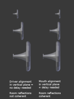
That is correct, but if you physically align all the diagrams in a vertical plane, then with straight horns you would not need any delay. But the horn mouths are then not aligned in a vertical plane due to the different length of the horns. If you align the mouths in a vertical plane you do need to delay.For the same sound emitting from all drivers, assuming the diaphragms are physically aligned,
It would take 0.002915s longer for the sound to clear the mid bass horn mouths vs the shorter upper mid horn.
Please note that time alignment is not the same as phase alignment though. Physically aligning the drivers along their acoustical centers only gets you so far.

acculution
https://www.acculution.com › single-post › 2017/08/23
#007: Time Alignment in Loudspeakers
acculution
https://www.acculution.com › single-post › 2017/08/23
Completely true, the end result should be phase aligned. My story here is that if you create different path lengths for reflected sounds because the mouths are not lined up, the end result is less coherent. That is my impression anyway after experimenting with alignment, but if someone has a better view, I would love to hear it.Please note that time alignment is not the same as phase alignment though. Physically aligning the drivers along their acoustical centers only gets you so far.
Hi, coherency of reflected sound breaks up as soon as the sources are not coincident. If you draw first specular reflections from a tweeter and a mid, whose mouths are aligned physically, their path length to ear from side walls would be equal if they are not toed in much (assuming different sized mouths) and ear is mid height of the two. Back wall would be fine if sides are fine. If you measure path lengths for front wall, floor or ceiling first specular reflections they would deviate. So, if not coincident about half of first reflections would be coherent while half would not, and most of higher order reflections wouldn't be either, there is more with some elevation than strictly at ear level. Diffraction signatures would differ as well, unless the physical objects were about the same so its a dream for other than single point source 😉 Not sure how much if any is audible though, perhaps it is depending on what the environment and positioning is, listening distance. Listen too far and the room sound is louder than direct sound and detail is just gone.
Last edited:
Not a better view but a different one. Some waveguides are designed to eliminate the early reflections or at least to reduce them, and in any case the close by and rearward walls can be treated.if someone has a better view, I would love to hear it.
In such cases the frontage can become a matter of the performance of the waveguides. Some want to be together and some want to be apart.
The next issue is to give them the preferred phase relationship for the right room output. This gives them time alignment because phase and time alignment tend to work together.
Last edited:
- Home
- Loudspeakers
- Multi-Way
- (mid)Bass horns and partially covered drivers