Hi
I have just ordered the Delta 1 + 2 and LCDuino for my Aikido, but will also use it for my DCB1. If you are concerned that DC fluctuations will interfere with the relay operations then you should connect the relay coils to a separate DC supply. AMB has provided for this. This also means you may use 12V relays in place of 4.5V relays. They explain how to do this in their documentation on their site. The only proviso is that the DC voltage must be .5V above the relay coil operating voltage.
I have just ordered the Delta 1 + 2 and LCDuino for my Aikido, but will also use it for my DCB1. If you are concerned that DC fluctuations will interfere with the relay operations then you should connect the relay coils to a separate DC supply. AMB has provided for this. This also means you may use 12V relays in place of 4.5V relays. They explain how to do this in their documentation on their site. The only proviso is that the DC voltage must be .5V above the relay coil operating voltage.
Hi Henryve and thank for your reply. At the end I have come to your own conclusion using a dedicate PSU at 12V. I hope that a new transformer in the same case of DCB1 doesn't generate any hum... as of now the DCB1 is absolutely silent and fantastic sounding.
I will prepare a new front panel for the LCD and the motorized pot and I will interface the delta 2 with the same connector for the switch. Actually having the remote control and the LCD is intriguing but if the LCDuino will decrease the performance will be easy to back to the original.
Regards
I will prepare a new front panel for the LCD and the motorized pot and I will interface the delta 2 with the same connector for the switch. Actually having the remote control and the LCD is intriguing but if the LCDuino will decrease the performance will be easy to back to the original.
Regards
Hi Henryve and thank for your reply. At the end I have come to your own conclusion using a dedicate PSU at 12V. I hope that a new transformer in the same case of DCB1 doesn't generate any hum... as of now the DCB1 is absolutely silent and fantastic sounding.
I will prepare a new front panel for the LCD and the motorized pot and I will interface the delta 2 with the same connector for the switch. Actually having the remote control and the LCD is intriguing but if the LCDuino will decrease the performance will be easy to back to the original.
Regards
Firstly: I think you actually need the LCDuino to control the Delta 1 and 2. Or else you have to develop your own way to control the Delta 1 and 2.
Secondly: You don't need big transformers (so no hum really) for the LCDuino PSU and the 12V for the relays. In fact, you could use the DCB1's transformer (15V) for the relays and pass it to a standard programmable voltage regulator. I am lazy, so I am just using their PSU also for the LCDuino setup with the 4.5V relays. It uses a small PCB transformer.
Sorry... I was not clear on my description... I will have (is on the way) the LCDuino and the relevant delta 1, the delta 2 for the switching of the 6 input of the mesmerize board and the motorized pot. Plus the dedicate delta 25 for the 5 PSU with a small PCB trafo. About the hum I am just a little scare adding another trafo in my actual pre... but we will see.
Thanks for your replies... appreciate! I will let you know...
Enrico
Thanks for your replies... appreciate! I will let you know...
Enrico
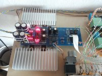
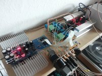
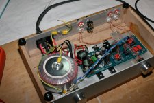
And another DCB1 Mezmerize has come to life!
A few comments on my build:
Here are some Numbers that I've pulled from the circuit when I was testing it with a DC benchtop supply:
+V_supply=18.09V -V_supply=-18.13V (from DC supply)
+V_10R_drop=1.35V +V_10R_drop=1.43V (divide by 10R to get current in A)
+P_10R=182mW -P_10R=204mW (dissipation of CCS resistors)
+V_reg=10.23V -V_reg=-9.49V (regulator supply voltage)
+V_3LED=5.42V +V_5LED=9.60V -V_3LED=5.45V -V_5LED=8.85V (voltage drop over LED chains)
V_output_L=1.1mV V_output_R=-1.9mV (DC output offset)
So far my build is looking good, noise free, well tempered, and it sounds very transparent. 😀
A few comments on my build:
The smoothing caps are Panasonic FC 2200uF 50V, I piggybacked two together to get close to the recommended 4700uF. The CCS resistors are 10R 5W thick film, so we're dealing with a moderate hotrod version here. The resistors in the signal path and for the regulator portion are Dale RN55D, caps are Nichicon Muse, expect for the LED string caps, they're some 0u47 Panasonic PP film caps. FETs are IRFP(9)140N, diodes are SF16. The 4 2SK170 JFETs for the buffer were all somewhere around 7.5mA IDSS, the others in the reg somewhere around 8mA.
The heatsinks are way oversized, but hey, why not.
- As I've mentioned earlier in this post, I'm using 221R gate stoppers (instead of 470R), and judging from what I'm seeing on my 20MHz analogue scope, it's not a problem (no oscillation) to use such a small value.
- Since I am pairing this Mez with a DCB1 blue edition (Hypnotize), which in turn is fed into and supplying a DCB1 style crossover, I have placed the volume control between the Mezmerize and the Hypnotize. At the Mez's input, instead of the pot, I have placed 22.1k Dale RN60D resistors from signal to ground, which in parallel with the buffer should form an input impedance of pretty much 20k. I have the impression that my source (DAC) likes the fixed resistance better than it did like the direct volume pot before.
- The source selector I took from my old BOZ build, and since I'm only using four inputs, I spliced the indicator LED's onboard supply into the ribbon cable to remotely power a LED which is indicating the selected input (LED's ground is individually switched through together with relay).
Here are some Numbers that I've pulled from the circuit when I was testing it with a DC benchtop supply:
+V_supply=18.09V -V_supply=-18.13V (from DC supply)
+V_10R_drop=1.35V +V_10R_drop=1.43V (divide by 10R to get current in A)
+P_10R=182mW -P_10R=204mW (dissipation of CCS resistors)
+V_reg=10.23V -V_reg=-9.49V (regulator supply voltage)
+V_3LED=5.42V +V_5LED=9.60V -V_3LED=5.45V -V_5LED=8.85V (voltage drop over LED chains)
V_output_L=1.1mV V_output_R=-1.9mV (DC output offset)
So far my build is looking good, noise free, well tempered, and it sounds very transparent. 😀
Attachments
Last edited:

The first time I participate in this forum. DCB1 I almost made, but I need advice. I have 3 sets of 4 mached JFET: 7.1mA, 7.0mA and 6.95mA. Please where is the optimal use of each kit.
Thanks, Matjaz
Thanks, Matjaz
Hi!
This is my first post here, but I´ve been following for quite some time.
Me and a friend have been building a Mez each, and we both have the same fault.
One of the led groups won´t light up. See photos for closer detail, and voltages.
This is my first post here, but I´ve been following for quite some time.
Me and a friend have been building a Mez each, and we both have the same fault.
One of the led groups won´t light up. See photos for closer detail, and voltages.
Attachments
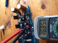

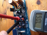
Carefully measure the voltage across each unlit LED.
If one is back to front it will show a much higher voltage drop. LEDs are not good blocking diodes and may be damaged by reversing them. Better to replace rather than trying to carefully remove it for re-use.
If all the LEDs are reversed, then power Down and use the Diode function on a DMM (sometimes the 2000mVdc scale can do this job) to determine the rough Vf of each diode. Each should read open circuit when you swap the probes. If all are OK then swap them around. This time they should not be damaged by the reverse voltage, since they all help each other.
Hi, AndrewT. And thenk you for you response!
All the leds are mounted correctly, and the all work. Tested!
However this group does not light up. New today is that they light up very shortly when powering on (I use a switch on the tranny), but then fade out and die.
I also get DC go all legs on the power gets when measuring from the centre points on the board, across to the mid leg go both the 240s and the 9240s.
I am a newbee, and at a loss 🙂
Thomas
Do you mean that should check whether I mounted them on their correct place on the pcb?
-Thomas
-Thomas
Yes, check that each one has the right type print on its body VS its correct position on the board.
They seem to be correctly placed, with the metal side pointing outward, transistors standing above the pcb.
The markings on the transistors are irfp240 y27k aq and irfp9240 y25w am
-Thomas
The markings on the transistors are irfp240 y27k aq and irfp9240 y25w am
-Thomas
OK. Also check there is no BC transistor in a K170s place by mistake, so we are sure about all the parts placing first.
After that put the DVM probes across the BE pins of the BC transistor on the dark LEDS side, it must have about 0.6V. If not, replace.
Then on the G,S pins of the MOSFET next to the dark LEDS. The one over the print "shunt reg". You must see 3-4V. If not, replace it.
After that put the DVM probes across the BE pins of the BC transistor on the dark LEDS side, it must have about 0.6V. If not, replace.
Then on the G,S pins of the MOSFET next to the dark LEDS. The one over the print "shunt reg". You must see 3-4V. If not, replace it.
Also with the power turned down and with the DMM in Ohm mode measure each K170 of the dark side across its outer pins. Must show 30-50R normally.
I thought I was finished project but I made a mistake and I need your help to fix it.
Some of the key data:
All LED light.
ACC 16.27V 16.28V
DC + 10.82V - 10.09 V
Offset R 1.1 mV L - 0.54 mV (How can I get it if relays do not work)
Hotrodded. I use 8.2 ohm resistors. Voltage across the resistor are:
+ 1.793 V - 1.685 V
And the problem. I used the NEC 12V relays that have the same pin configuration like Omron. I hear the relays to switch but there are not electrical connection. What can I do.
I also used the 15, 0, 15, 150VA transformer, because I thought to give in the same enclosure the phono stage. I will change transformer for smaller. How VA would be optimal in the context of my other data.
Thanks Matjaž
Attachments

Last edited:
- Home
- Amplifiers
- Pass Labs
- Mezmerize DCB1 Building Thread