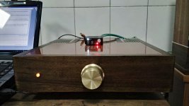
Congrats. Its a task to correctly assemble that pot.
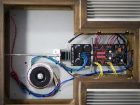
I see that the box is already mains earthed for safety so if you get no hum or buzz in your system just leave the PCB ground alone.
10 Ohm is generally OK for the Mez's CCS. What is the voltage drop across the positive side and negative side Rset 10R?
Let me know so if you will try some more current to evaluate, you could balance tolerances too.
10 Ohm is generally OK for the Mez's CCS. What is the voltage drop across the positive side and negative side Rset 10R?
Let me know so if you will try some more current to evaluate, you could balance tolerances too.
Hi Salas,
The voltage drop across 10R are 1.73V on one resistor and 1.93V for the other one. Is it normal to be this much of difference between the two?
Last edited:
Yes.
The mosFETs have a very wide production variability in the Vgs. You are also comparing -Vgs to +Vgs, that introduces another variable.
What you can do is calculate the current for the two CCS. Then adjust the 1.73V version by adding a parallel resistor to your fixed 10r, so that you increase the CCS current up to nearer the 1.93V version. This gets the output FETs passing similar currents and thus similar gm.
Except that the -ve regulator is very different from the +ve regulator and similar currents may not give similar performance.
Hi Salas,
The voltage drop across 10R are 1.73V on one resistor and 1.93V for the other one. Is it normal to be this much of difference between the two?
Thanks. Yes its normal due to different VGS readings between MOSFET samples, especially between "complementary" types.
So if you will ever try boosting it to about double the now current to check how you will like it subjectively, use 4.3R on the 1.73V side, and 4.7R on the 1.93V side. Use 3W resistors mounted a few mm board proud to ventilate better.
Installing LEDs. How do you tell which way the LED is facing??
I know longer wire is positive.
I am trying to utilize the pcb markings but not sure when I look at the LED.
I know longer wire is positive.
I am trying to utilize the pcb markings but not sure when I look at the LED.
There is a straight edge on each LED's rim. And there is a D symbol near each LEDS group on the board. Orient each group according to each D.
Also the led will have a long and short lead. Its the same polarity as long and short leads on electrolytics.
Long is positive.
Long is positive.
Ok... So.... I am just gonna assume the short lead is the same side as the "straight" edge of the "D"
Right? Otherwise I would need a pic or something. I could argue both sides are straight.
I get what side is positive. When someone starts quoting electrolytics, they are going way beyond where I am at.
Right? Otherwise I would need a pic or something. I could argue both sides are straight.
I get what side is positive. When someone starts quoting electrolytics, they are going way beyond where I am at.
I always forget for some reason and electrolytics have a minus sign on the short leg side just like leds. Since there is always a pile of electrolytic caps around I always have a reference. Its okay bud...we'll make it through remedial electronics together. However if I was suggesting projects I would say to build the original B1 by Nelson Pass first. Every single part in that simple circuit is a valuable lesson. Plus its easy to build even on protoboard.
Thanks udailey. Thanks sala.
It's just another example of being unsure about the really simple because one, cautious, person has not seen it done before.Thanks again.
It's just another example of being unsure about the really simple because one, cautious, person has not seen it done before.Thanks again.
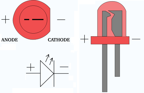
Not all LEDs have the flat side. The VAOL-3HCE4 LEDs from Mouser I used is completely round. So I just aligned the short lead with the flat side of the symbol on the PCB.
Notice the big "anvil" on the negative/cathode lead. This can be seen in many LEDs. Sometimes you can also see the wire that connects the +ve/anode to the anvil.
This big anvil holds the reflector that bounces out the light.
3mm LEDs usually do not have enough "body" to show the flat side. LEDs that have been trimmed won't show the "long" lead.
The anvil can be likened to the - bar of the -ve lead and matches the bar of the diode symbol
This big anvil holds the reflector that bounces out the light.
3mm LEDs usually do not have enough "body" to show the flat side. LEDs that have been trimmed won't show the "long" lead.
The anvil can be likened to the - bar of the -ve lead and matches the bar of the diode symbol
Not all LEDs have the flat side. The VAOL-3HCE4 LEDs from Mouser I used is completely round. So I just aligned the short lead with the flat side of the symbol on the PCB.
 yes that was part of how I was confusing myself. Thanks for all the posts. I am now the LED master!! 😀
Hifi Rookie,
I read this thread before I started my build, and found very useful info for beginner.
DC-Coupled B1 Buffer Build
Please note that it is the same build, but different version of the PCB.
I read this thread before I started my build, and found very useful info for beginner.
DC-Coupled B1 Buffer Build
Please note that it is the same build, but different version of the PCB.
Regarding caps.
I have the BOM 35v 4700uf nichicon.
I also have some 35v 4700uf gold tune nichicons but as you know they do not fit exactly( I have the dcb1 mez board).
What is everyone's thoughts regarding sound quality difference and if you go with gold tune how do you best install them?
I have the BOM 35v 4700uf nichicon.
I also have some 35v 4700uf gold tune nichicons but as you know they do not fit exactly( I have the dcb1 mez board).
What is everyone's thoughts regarding sound quality difference and if you go with gold tune how do you best install them?
Last edited:
- Home
- Amplifiers
- Pass Labs
- Mezmerize DCB1 Building Thread