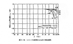
Here is a frequency chart of a cartridge with an 0.5mil stylus, showing how the frequency characteristics are affected by tracking force and by the inner vs. outer grooves.
The upper three lines marked 1gr (grams), 2gr and 3gr are for the outer grooves. The lower three lines marked 1gr, 2gr and 3gr are for the inner grooves.
As a separate issue, the cartridge's frequency response will also be affected by the operating temperature, mostly due to how the characteristics of the rubber dampers change with temperature.
Attachments
I've always wanted a Moerch, maybe one day. I too went MC in the late 80s and it was only after 20+ years I realised that the MM I abandoned actually had a more advanced stylus than anything I had had since at 9x the cost. This got me thinking, so I started this thread.
JCarr: I suppose that graph leads to a questions
1. what is the mechanism for this. In particular why does high VTF increase HF loss, that doesn't immediately make sense.
2. Is this corrected for in mastering (in which case which is the correct profile for a cartridge)
JCarr: I suppose that graph leads to a questions
1. what is the mechanism for this. In particular why does high VTF increase HF loss, that doesn't immediately make sense.
2. Is this corrected for in mastering (in which case which is the correct profile for a cartridge)
The most obvious cause of HF loss at 3G is increased contact pressure spreading contact horizontally. This could either be due to vertical contact not actually being vertical, or due to the stylus radius
If the contact with the vinyl has a finite horizontal width, it will reduce output from tracing a high frequency sinewave cut, a bit like the sin(x)/x of digital
Any here know if all the OM cartridge bodies are the same? I found an OMB variant I got somewhere. Also, I found a Ortofon FF15 XE MK II, which also require a new needle.
With regards to MCs. It seems that tracking ability of many MC cartridges are not that great. I have friends with expensive VDH cartridges (Condor) and I always hear tracking errors when they play records for me. They don't seem to hear it 😕. But, it might just be bad cartridge alignment even though tests like the ones shown in the Hifi-world magazine do indicate that many MC cartridges doesn't track that great.
Mogens
Hmmm...... except we all know the f response of real vinyl playback versus VTF doesn't meaningfully vary, over a wide range......... and certainly not on the scale portrayed there.Here is a frequency chart of a cartridge with an 0.5mil stylus, showing how the frequency characteristics are affected by tracking force and by the inner vs. outer grooves.
The upper three lines marked 1gr (grams), 2gr and 3gr are for the outer grooves. The lower three lines marked 1gr, 2gr and 3gr are for the inner grooves.
As a separate issue, the cartridge's frequency response will also be affected by the operating temperature, mostly due to how the characteristics of the rubber dampers change with temperature.
Trying to piece together what the graph might mean, there seems to be a reference to Young's modulus Eo and a value stated. Just a guess, but perhaps this is some form of lab indentation test, that would show (as expected) relative indentation reduces with increases in frequency and VTF ?
The Y axis is in dB, so has to be a ratio.... I guess indentation amplitude at frequency f divided by static indentation ?
What such a test should show is that the elastic properties of vinyl are time domain dependant, being an elastomer. So, for a given amplitude and force, vinyl gets stiffer with increasing frequency.
As to real vinyl playback, even in an unmodulated groove, a stylus traverses its own contact length along the groove wall perhaps 250,000 times per second. Or, from indentation of the groove wall perspective, each point on the groove wall is exposed once to a very short pulse of force for few µS. If that were repetitive (which it isn't from vinyl wall point of view), a representative frequency would be about 250kHz. At which frequencies vinyl is effectively rigid, and I think that might be what this graph eludes to.
LD
There are two main classes of OM body. Solid pin (OM) and split pin (5x0 series, SuperOM and 2M). There are supposed advantages to the split pin but no one outside of otofon marketing has ever published any results. As I have an example of each, and LD will have soon there is a fighting chance we can find some data.
Aside: there are also DJ bodies with higher output and I have a couple of those to experiment with to try and sort out what the pecking order is and if there is any real audible difference.
Aside: there are also DJ bodies with higher output and I have a couple of those to experiment with to try and sort out what the pecking order is and if there is any real audible difference.
Thanks Bill, I wonder what the split pin actually means. I forgot I have an 2M Red here. Any electrical measurements I can do that would be interesting?
Mogens
Mogens
Internet is completed shagged here at the moment, but if you look here 500 Series this is the best official information on the split pin I have yet found. Must be some patents somewhere I have not dug out.
AFAIK the Ortofon split refers to a slot along the ferromagnetic tube that is the moving armature, presumably intended to reduce eddy currents. Perhaps the same trick is applied to the pole pieces in the coil core?Thanks Bill, I wonder what the split pin actually means. I forgot I have an 2M Red here. Any electrical measurements I can do that would be interesting?
In any event, IIRC from a few years back, I once worked out that eddy current losses are proportional to slew rate of programme material. I can't recall why off the top of my head though - I'll chew it over again. So I might look for difference in slew rate performance, which might show up as level dependant hf response?
Seldom discussed, slew rate performance........... but a big part of audio generally. And its derivative.........
LD
Thanks Bill. I Googled and searched the Ortofon website and didn't find anything. After you mentioned it I took removed the needle from both the OMB and the 2M and noticed that the 2M had "holes" in the end of the 4 rods that is visible compared to the OM.
Mogens
Mogens
Oddly did find your early musings on that that were not purged. You were dismissive of laminated cores in your young pup days 🙂.
Probably because flux changes involved are so small, plus it's not clear what one should measure to observe any difference and normal observations appear fine.....You were dismissive of laminated cores in your young pup days 🙂.
I still haven't looked at slew rate performance with/without the modifications for an OM body, but I think I got happy that is where any differences might lie.
I'll try to recall the theory as to why.........
LD
I am still confused about the 'midrange' dip that eddy currents are supposed to cause. If I get the rest of the soldering done tonight I'll have a dig back through my notes as ISTR it was all explainable with inductance differences. But my memory could have failed me!
Slight recall but out of the edit window. I need to check but pretty sure the midband dip could be explained by the higher self inductance of the solid pin/non laminated model. I need to check back on George's measurements of his M97 inductance.
There are claims out there that permalloy permeability can fall by up to 1/10 from 1kHz to 10kHz
I need to check but pretty sure the midband dip could be explained by the higher self inductance of the solid pin/non laminated model. I need to check back on George's measurements of his M97 inductance.
Inductance eh? Hmm!
Here is what I have shown in the past.
After some work I have done with power transformers, I can say that inductance estimation is only approximately useful if the level of the test excitation signal is close to the voltage level that the DUT is to work under.
That said I have to run a set of impedance sweeps on the M97 each with a different level of excitation signal (I’ve said it again but I haven’t done it).
mechanical resonance in MMs
mechanical resonance in MMs
mechanical resonance in MMs
mechanical resonance in MMs
George
- Home
- Source & Line
- Analogue Source
- mechanical resonance in MMs