So for all you guys with test data and no way to determine exactly the "excess time" or "time of flight" with your software how about this. Because the number inserted into the software seems more or less arbitrary, what about putting in a number which causes either 0 degrees or 90 degrees to appear at resonance or at the center of the energy pass band? Center of the energy pass band = square root of F-low * F-high. Just to so I might see a graph something like I am used to... maybe please?
Hi Sum,
My measurements are Zero Locked in Holm impulse. Ie after measuring the woofer, the auto mechanism is turned off and the same zero point used for the tweeter. With this in mind you can see that the drivers are time aligned 🙂
I believe that Holm should be able to show the time of flight as well (it simply detects the start of the impulse and makes that time zero, unless you tell it otherwise. Whether I can get that information from existing measurements or have to do others I'm not sure (If I have to do new measurements it could be a while, as in possibly weeks). If I've got time I'll see what I can come up with.
I'm still not seeing the phase flip in the measurements I posted, I personally think that the dip around 5.5K is a diffraction rather than a driver artifact (and I think that the impedance measurement backs this up), but I'll try getting you a different representation of the data if that helps you to get your point across 🙂
Tony.
Seems hard to do since the FR is not always ideally smooth. If we assume that the response is minimum phase, then lots of tools will allow you to do it. Additionally, since the listeing position is very seldom at design point, so probably such small error will not cause significant problems, and we can shift the drivers around about for final adjustment.

In the plot above Time Zero is set for Largest Peak / Auto Detect
Here's the same tweeter with Time Zero set for Casual Impulse / Auto detect,
which puts the f's closer to 0 degrees

Here's the same tweeter with Time Zero set for Casual Impulse / Auto detect,
which puts the f's closer to 0 degrees
sba- and others- thanks for those plots and thoughts- I am afraid I see circular logic- "If minimum phase is assumed then all this measurement are valid" And I agree with this if it could be shown to be true. Unfortunately I have seen nothing here to cause me to believe all these transducers are minimum phase other than the assumptions. This also agrees with what I said earlier about making the assumption which supports the conclusion. Sorry guys but I am just not buying it. I know impulse testing is the method of great popularity but I also know I never used it because I could never validate any impulse speaker testing system against carefully measured standards using no fancy tricks other than gating noise or two tone testing. So all you and I disagree- I believe impulse testing data is just about useless for audio transducers and everyone else believes the results are accurate and precise. I feel like Galileo... and blasphemy of the church of impulse. I see the conflict clearly now. There is no argument I wish to make at this time. There is only the job of showing impulse testing as done by REW and HOLM does not lead to accurate results. That will be very easy once I set up for it as it is clearly the case in my experience.
So does CBT mean constant beamwidth transducer or controlled blind test? And what is the popular "CD" (constant directivity and not compact disk) mean now days and is that the same as constant beamwidth transducer? I am not trying to give anyone a hard time with these two terms. Just people change the definitions with time, as the nature of language, and just do not know what is popular now. If someone would be so kind as to spell it out clearly? Thanks!
So does CBT mean constant beamwidth transducer or controlled blind test? And what is the popular "CD" (constant directivity and not compact disk) mean now days and is that the same as constant beamwidth transducer? I am not trying to give anyone a hard time with these two terms. Just people change the definitions with time, as the nature of language, and just do not know what is popular now. If someone would be so kind as to spell it out clearly? Thanks!
It would seem quite a stretch to treat any misunderstandings you may have about linear systems theory as turning you into some kind of religious martyr. I have no knowledge of the particular drive units you have measured, so cannot comment on them, but swept sine response measurement systems, which include the REW and Holm software you have mentioned but also most others (even TEF at its core uses a swept sine, albeit differently processed) do not assume or require the systems they measure to be minimum phase. Correctly determining measurement delay is of course important for meaningful display of absolute phase, but getting that wrong does not change the system being measured nor would any measurement system I am aware of generate results that would suggest otherwise. I've put some info about minimum phase in the context of room measurements here, but I'm happy to offer any help I can on questions relating to measurement systems in general and REW in particular.I know impulse testing is the method of great popularity but I also know I never used it because I could never validate any impulse speaker testing system against carefully measured standards using no fancy tricks other than gating noise or two tone testing. So all you and I disagree- I believe impulse testing data is just about useless for audio transducers and everyone else believes the results are accurate and precise. I feel like Galileo... and blasphemy of the church of impulse. I see the conflict clearly now. There is no argument I wish to make at this time. There is only the job of showing impulse testing as done by REW and HOLM does not lead to accurate results. That will be very easy once I set up for it as it is clearly the case in my experience.
Hi Sum,
I certainly don't beleive that impulse testing is useless, but I don't necessarily believe it is accurate and precise either, just a read of Joe D'appolito's "Testing loudspeakers" chapter on computer based measurements should show that digital sampling is anything but precise!!! It involves a heap of interpolation, there just aren't enough samples to get a truly accurate measurement of the waveform (accurate meaning no interpolation).
So where does that leave me? Well I used impulse testing for measuring my drivers (both the SPL and the impedance). I used these measurements to simulate my crossover. I went and bought the components and built the crossover. I then measured the SPL using the impulse again. The result?
Nearly exactly the same as the simulation. Now I would call this far from useless! In fact I would also venture that if the frequency response data and the impedance data were inaccurate due to having used an impulse response for measurements then it would not have been possible for the simulation to predict the response that would result.
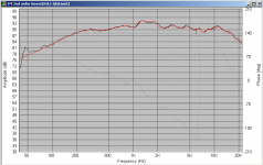
Attached is the actual measured response of the implemented crossover (black) and the simulated response (red) which was simulated from the individual drivers measurements using speakerworkshops crossover simulation capabilities. SPL measurements were made using holm impulse, and impedance measurements were made using speakerworkshop.
Would the speaker measure differently using a different test methodology? Probably. Would that different test methodology mean that I could build a far superior speaker? Probably not IMO.
I'll use as an example photography (one of my other interests). In my oppinion the key to getting good results is not having the best equipment, but knowing what the limits of your equipment are, and ensuring you work within those limits.
Not all of us have the luxury of anechoic chambers, or huge rooms or outdoor spaces that are suitable for doing measurements. Impulse responses and gating allow the rest of us to make measurements that are in my oppinion invaluable in helping design our speakers. Without Impulse responses I would probably never have been able to design a decent crossover for my speakers. The current one is not necessarily the final one, but the fact I've been listening to it for probably 3 months now tells me that it isn't too bad 😉
Tony.
I certainly don't beleive that impulse testing is useless, but I don't necessarily believe it is accurate and precise either, just a read of Joe D'appolito's "Testing loudspeakers" chapter on computer based measurements should show that digital sampling is anything but precise!!! It involves a heap of interpolation, there just aren't enough samples to get a truly accurate measurement of the waveform (accurate meaning no interpolation).
So where does that leave me? Well I used impulse testing for measuring my drivers (both the SPL and the impedance). I used these measurements to simulate my crossover. I went and bought the components and built the crossover. I then measured the SPL using the impulse again. The result?
Nearly exactly the same as the simulation. Now I would call this far from useless! In fact I would also venture that if the frequency response data and the impedance data were inaccurate due to having used an impulse response for measurements then it would not have been possible for the simulation to predict the response that would result.
Attached is the actual measured response of the implemented crossover (black) and the simulated response (red) which was simulated from the individual drivers measurements using speakerworkshops crossover simulation capabilities. SPL measurements were made using holm impulse, and impedance measurements were made using speakerworkshop.
Would the speaker measure differently using a different test methodology? Probably. Would that different test methodology mean that I could build a far superior speaker? Probably not IMO.
I'll use as an example photography (one of my other interests). In my oppinion the key to getting good results is not having the best equipment, but knowing what the limits of your equipment are, and ensuring you work within those limits.
Not all of us have the luxury of anechoic chambers, or huge rooms or outdoor spaces that are suitable for doing measurements. Impulse responses and gating allow the rest of us to make measurements that are in my oppinion invaluable in helping design our speakers. Without Impulse responses I would probably never have been able to design a decent crossover for my speakers. The current one is not necessarily the final one, but the fact I've been listening to it for probably 3 months now tells me that it isn't too bad 😉
Tony.
Attachments
The conclusion was not made based on assumptions, that's a false argument. The conclusion that most if not all typical dynamic drivers are minimum-phase is based on the years of measurements made have been shown to be minimum-phase. You may not like nor agree with the conclusion, but there is not yet any conclusive data that contradicts the years of measuring and comparison to models created that accurately match the measurements.sba- and others- thanks for those plots and thoughts- I am afraid I see circular logic- "If minimum phase is assumed then all this measurement are valid" And I agree with this if it could be shown to be true. Unfortunately I have seen nothing here to cause me to believe all these transducers are minimum phase other than the assumptions. This also agrees with what I said earlier about making the assumption which supports the conclusion.
Were this not the case, the application of minimum-phase crossovers simply would not work.
As for interpolation, if you want to investigate to much higher resolution, it's easy to set up a measurement system that uses 192K sampling rate cards that can yield impulse sample point separation of 0.0000052 sec. With the Nyquist limitation, this is still valid to 96KHz, way beyond what any mic is going to offer. This will provide more than sufficient resolution.
Add to that the capability of systems that can, even in an anechoic environment, process the impulse response to eliminate the anechoic portion of the measurement that allow for much longer impulse windows so that the FFT can provide more than sufficient resolution previously limited by the first reflection.
If someone is that concerned about interpolation, I would suppose that that person will never use digital audio of any sort to assess the sound of their system since its all a process of sampling. The reproduction is in essence interpolation since the audio out is a continuous waveform whlie the input for the D/A stage is discrete, no difference than what a measurement system does. And I would add, all phase information required to reproduce the original event is inherently embedded in those sample points.
Dave
As for interpolation, if you want to investigate to much higher resolution, it's easy to set up a measurement system that uses 192K sampling rate cards that can yield impulse sample point separation of 0.0000052 sec. With the Nyquist limitation, this is still valid to 96KHz, way beyond what any mic is going to offer. This will provide more than sufficient resolution.
Dave
Hi Dave,
That's what I thought too before reading the chapter in Joe's book, I'm not saying that it isn't enough to get useful measurements far from it, but the whole sampling thing IF I remember it correctly (and as you point out, any form of digital audio), was rather more crude but at the same time tricky than I had previously realised. It was after reading this chapter that I got an inkling as to why some are so adamant that analog is superior. I only use digital myself BTW.
Tony.
It's just a matter of understanding the system and its limitations. All measurements systems, no matter the type, have limitations, just as all audio recording systems have theirs. Heck, just look at how many microphones one has for choice, then look at the wide range of response characteristics they have. You largely choose which coloration best suits your desires. 🙂Hi Dave,
That's what I thought too before reading the chapter in Joe's book, I'm not saying that it isn't enough to get useful measurements far from it, but the whole sampling thing IF I remember it correctly (and as you point out, any form of digital audio), was rather more crude but at the same time tricky than I had previously realised. It was after reading this chapter that I got an inkling as to why some are so adamant that analog is superior. I only use digital myself BTW.
Tony.
Dave
It would seem quite a stretch to treat any misunderstandings you may have about linear systems theory as turning you into some kind of religious martyr. <snip>
JohnPM- really let us try to avoid insulting. According to the many I have worked with I understand linear and acoustic models better than just about anyone. Not my words. I do not understand a lot of these graphs as shown in this thread simply because they do not fit into either of those models well or any other model that I have personally validated. Thank you for your offer to help. It is not religious for me, it is fact versus fiction. The fiction being based on assumptions which support the conclusion. I do not make assumptions where ever possible I apply rigor.
For most testing I use the IASYS because it is fast and easy and designed by some of the smartest and most well versed persons I have ever known in audio. On single drivers it works flawlessly though on complete multi-way systems it can make errors which have been validated and may be watched for in results. My TEF machine gives accurate results but what do the results mean? TEF is very difficult to go from data to useful information. Impulse testing is used all the time here for electronic filter analysis but never for transducers.
So again we just disagree of what is valid and what is not. Is anyone here ready to take on the validity of the very rigorous IASYS testing? If I ever make another audio speaker product, at that time it will be obvious who I am and obvious when I get done ripping this impulse testings down to the almost nothing they are. No offense to any of you at all.
Actually, I want to thank each and every one of you for taking the time to respond to my post and to "re-educate" me in the current fads of loudspeaker testing and beliefs. It really has served well for my goal of learning on DIYaudio.
Thank you all so much
=SUM
OK, you've thrown out a challenge, can you provide more details?
For example: Take a driver that you think exhibits a problem that a measurement system like IASYS will show. Measure and show us the results. Then measure with an impulse software and show us the differences. What is IASYS or similar doing right that the impulse systems are doing wrong?
The main problem here is that you have some very interesting claims, but that's all. We never get to see the least little graph or measurement. Help us out. Most of us are here to learn and are actually open minded, despite appearances. 😉
Some real comparisons of different measurement systems and what they may be doing right or wrong would go a long way. Just talking about it without real examples doesn't get us very far. Data would be a BIG help.
measurement system like IASYS will show.
Not what you would expect. Read the IASYS manual and take a look at the phase resolution among other things. It's a quick read. I took a look at it a week or so ago.
http://www.sound-better.net/Support/Manuals/Pro/Owners_Manual_IASYS.pdf
Rob🙂
Isn't TEF somewhat similar to CSD? But presented differently?... My TEF machine gives accurate results but what do the results mean? TEF is very difficult to go from data to useful information. Impulse testing is used all the time here for electronic filter analysis but never for transducers.
...
=SUM
It is quite interesting though that you mention this. My interest would be how would signal transfer through the remaining energy being released. The fact that you bring this up now really promted me to start looking back at the time energy curves to compare them with some Klippel measurements to see if something will stand out or not. Thanks for bringing this up.
Last edited:
Here's one enlightening line:Not what you would expect. Read the IASYS manual and take a look at the phase resolution among other things. It's a quick read. I took a look at it a week or so ago.
http://www.sound-better.net/Support/Manuals/Pro/Owners_Manual_IASYS.pdf
Rob🙂
That speaks volumes.Iasys does not require the knowledge of acoustics, electronics, or physics previously needed to decipher frequency and time domain analyzers.
Dave
Pano, et al, the other thing to throw into the mix is that most modern impulse systems are not impulse systems, they're MLS. The autocorrelation then yields the impulse, but at a higher S/N for a given measurement time.
This whole discussion is pointless. None of what SUM says is correct. This whole topic has been thoroughly evaluated via dozens of AES articles, etc. HOLM is precisely correct and any system that agrees with it is also precisely correct (that would be most of them). If you do not agree with HOLM, then you are wrong. There is no issue with "interpolation", there is no phase anomaly with "impulse testing" (although no one would actually use an impulse to test, its just a phrase.)
Read the journals if you want to find out the facts, or listen to someone who knows. Don't listen to people who claim advanced knowledge that none of the rest of the world has.
Read the journals if you want to find out the facts, or listen to someone who knows. Don't listen to people who claim advanced knowledge that none of the rest of the world has.
- Status
- Not open for further replies.
- Home
- Loudspeakers
- Multi-Way
- Measurements: When, What, How, Why