The problem with both RickRay's and your measurements is the total noise which is higher than what your estimated noisefloor predicts. In your case the total noise is less than half of what RickRay had but still based on the total noise your LNA is comparable to a 40 ohm resistor which corresponds to 0.8nV/rtHz. Due to the high LNA noise a very lengthy averaging is required to eek out a "noisefloor" but at least in RickRay's case the "noisefloor" looked suspicious. You haven't shown LNA noise from 10Hz to 20kHz so difficult to tell if your noisefloor looks more sensible.
Unless the LNA (or ADC) noise is toned down the noisefloor estimations are quite irrelevant. RickRay's LNA has a noise limit at 270nV. Your LNA seems to have a limit at 112nV. Basically you cannot reliably measure noise that is well below those limits. You can of course make relative comparisons between DUTs at some limited bandwidth but based on that you cannot tell which DUT has the lowest noise within audio bandwidth.
Yea, somethings not right with my LNA, I'm going fishing for a couple days and will track down the issue after some time off.
I do not have the experience to know if and when such performance is required. I'm just glad it exists as an option. Also got to learn a lot on the way.
Here is an example of issues noise measurements can reveal. Few years back I built a dual switching regulator (+15V/-15V) using LT3471 boost/inverter and TPS7A regulators. Sort of a "demi" SilentSwitcher (i.e. without 5V output). Later when I bought a real SilentSwitcher which uses same chips it was possible to "validate" my design against it.
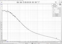
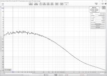
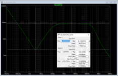
On the +15V side my version had slightly lower noise (about half of SilentSwitcher). But on the -15V side things looked different. The first attachment shows the noise of my -15V version. The second is the noise of -15V on the SilentSwitcher. As can be seen from 100Hz to 5kHz my version has lower noise but below 100Hz SilentSwitcher is clearly better. As it turned out I had not followed the datasheet recommendations to a tee but had used similar layouts for both positive and negative regulators.
Please note that within audio frequencies the noise levels on these regulators are in the "LM317+Cadj region". So these measurements should be no problem even for RickRay's LNA 😀
Attachments
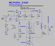
@jackinnj - can you post a schematic of what you breadboarded? The circuit Trileru and myself are using has a few changes. We used a 4.7uF film cap instead of a 1uF on the output. On the input we did not use C1 or R1, nothing drastic, but it is slightly different.
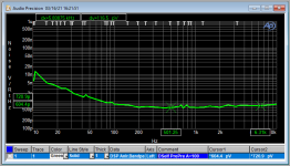
Here's the Self Pre-Pre -- only bread-boarded. Note that the output of the Self Amplifier is 1uF and 10K. The 10K is in parallel with whatever input impedance your measurement apparatus might present. The 1/f corner is ~200Hz
Thank you!
How many 2N4403 did you use, 3 or 4?
@jackinnj - can you post a schematic of what you breadboarded? The circuit Trileru and myself are using has a few changes. We used a 4.7uF film cap instead of a 1uF on the output. On the input we did not use C1 or R1, nothing drastic, but it is slightly different.
You have to protect the inputs of the PNP's. U4 was an OPA604, not TL071
Attachments
Here's the Self Pre-Pre -- only bread-boarded. Note that the output of the Self Amplifier is 1uF and 10K. The 10K is in parallel with whatever input impedance your measurement apparatus might present. The 1/f corner is ~200Hz
The AP screen shot comment states "A=100". Is that correct or is it a 60dB version?
Here is an example of issues noise measurements can reveal.
Note that the LNA's 1/f performance can get you into falsely concluding that your supply is abundant in LF noise.
For Keysight's high end DVM's you obviously want the low frequency noise to not corrupt measurements. For Audio, if you are into great organ music below 32Hz you won't even notice.
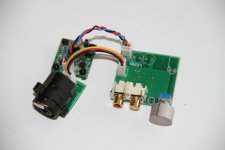
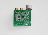
Yes, but in this case the LF noise is well above LNA's noise so no problem for measurement. And as I have shown before the LNA I'm using has a shallow 1/f curve (with no impedance peak 😉). I built the switching PS just for testing purposes. It was not meant for enhancing the listening experience of César Franck's organ works 😀. Lately it has found a happy home powering 2 victoresque (vicnic's design, my layout) low distortion oscillators (PS shown in picture behind the XLR).
Attachments
Last edited:
You have to protect the inputs of the PNP's. U4 was an OPA604, not TL071
I'm back from fishing, had great luck, caught a couple 50lb. spoonbills.
The circuit you show is close but different. Change R8 to 3.3k for +60dB gain. Remove R10. Add a 100R between R9 and OUT. We put a 22pF on the NE5534 between comp and output and connected C/B pin to output. BTW, we used a 220uF for C2.
I do not have enough knowledge to know how those changes would effect the circuit. I would imagine that increasing gain would increase noise from the higher resistor noise.
I would imagine that increasing gain would increase noise from the higher resistor noise.
LTSpice sim shows a decrease in noise when going from x100 to x1000.
edit: with 3x2N4403 and NE5534A (A version is lower noise I think) the sim shows 0.59nV/sqrtHz for x100 and 0.49nV/sqrtHz for x1000. With a 4th 2N4403 it drops to 0.45nV/sqrtHz (x1000).
Last edited:
I also tried using a OPA2604 instead of the NE5534 in LTSpice and noise is more or less the same. Not sure how accurate the models are. I used the NE5534A model from TI's website:
NE5534A data sheet, product information and support | TI.com
NE5534A data sheet, product information and support | TI.com
- Home
- Amplifiers
- Power Supplies
- Measurement data and techniques for Elvee's De-Noizator: all implementations