They could have replaced the LEDs with half current mirrors (letting the JFET do all the work), and thereby guaranteed that the LTP tail currents in the two diffamps were identical. But then the signal current gets converted to a signal voltage and applied to a pair of BJTs, one NPN and the other PNP.
Hi PRR,
Granted, but you do the best you can instead of giving up. Getting tight matches does matter in practice, and as you've noted, can have a large effect on distortion performance. As far as tail current control is concerned, I haven't really examined that circuit closely. So that is yet another issue with that design I guess.
It didn't start out as a great design, so it isn't surprising there are more issues.
-Chris
@reddish75 that's an excellent match! 2mV is 1% in your case.
I'm pretty bad at the maths side of things, could you tell me the formula to work this out?
Thanks

Hi,
Yes, that would be a great deal more stable for tail current. The most important concern is short term stability and the LED was chosen to compensate for temperature of the transistor. Because the comparison is made as a balance, the value of current over time isn't important really. I did consider being able to hammer the tail current to known values, but this won't affect the match. Part of designing this wasn't to make a perfect instrument but rather to make a testing device that would give very accurate results while being cost effective. The CCS for tail current was important to increase CMRR to make imbalances show up more. I could have used a resistor but it wouldn't be as sensitive then. So the impedance of the tail current source is more important than the actual value (within reason) at any given time.
I recognised the trap of making everything as perfect as it could be early on and had to reign myself in. It was boiled down to what mattered most and as long as the current is in the range of what you select, it doesn't really matter. Improving this will not hurt, so go for it.
I have designed stuff not so much to be perfect but down to a price.Hi,
I recognised the trap of making everything as perfect as it could be early on and had to reign myself in. It was boiled down to what mattered most and as long as the current is in the range of what you select, it doesn't really matter. Improving this will not hurt, so go for it.
In my experience that can cause problems. Lack of decoupling, cheap fake components etc. causing returns.
Then having to botch extra decoupling beneath pcb's. not very professional.
Sometimes you don't see the real problems until something is built and well tested.
Hi Nigel,
So true. This design has been built at least three different times by myself, then by many more people with different PCB layouts. I learned to keep things reasonably simple while looking after the factors that really matter. Getting creative to save money tends to create issues.
There is no end to bells and whistles you could add. Call it feature creep, but at the end of the day you simply want to see if two transistors are closely matched. That is all it has to do.
The most critical parts would be the 100 ohm collector resistors, 0.1% low TC metal film, 1/2 or 1 watt size. The 10K base resistors are again 0.1%, but can be 1/2 watt units. The LEDs are low efficiency red LEDs, 3mm, the transistors are TO-126 case style that don't have to handle more than an amp, even 1/2 amp should be fine. A higher gain part would be preferred, but not Darlington. I think I used 1K1 (not critical) resistors to bias the LEDs based on about 10 VDC plus and minus supplies. The emitter resistors are selected to set tail current.
I had a quick look. The resistors below the 1K1 values (and it isn't critical) are to set the tail current. They will differ depending on the transistor E-B drop and the voltage reference used. Speaking of the voltage reference, A red LED (low efficiency) was chosen to partially compensate for the temperature coefficient of the E-B junction on the pass transistors. A voltage reference IC will not do that. Also, the 3mm LED originally used does fit in the mounting hole for a TO-126 transistor and we want to keep them at the same temperature so they compensate for each other. This combination may well be more stable than using a voltage reference, but it is up to you.
The original design was to pass a relatively constant current through the pair of test transistors. This current only needs to remain in the ballpark of the intended current but remain stable over the time you are testing. A slow drift really won't affect things when checking for balance (or match). The red, low efficiency LED was picked because at a range of current, the temperature coefficient is similar to the pass transistor, which means a low rate of current drift for the combination. It does so at low cost and easy availability for the future for new builds or repair. This design is well over 20 years old, and I have made several as I wore them out through heavy use. Specialty parts would have been discontinued, so going this route was a good plan in hindsight.
You can add complexity and bells and whistles if you want. For example, using a voltage reference IC and an op amp with a pass transistor, you could hammer the tail current to a specific value and use digital control. Okay, but why? Now you have an exact tail current with next to zero drift and probably higher noise (that doesn't matter actually). Certainly higher expense and bragging rights. But look at what you are doing here. All you are doing is to run a pair of transistors at a stable current with high tail impedance so that differences are more apparent. You only need to compare the two currents to see if they are balanced (ie - they match). That's all, that's it. The original circuit does this very well and at low cost.
Now, if you wanted or needed to measure beta of the balanced pair, you could do that by knowing the emitter current and the base current (by measuring the drop across the base resistor). Measuring across the collector resistors gives you a good idea what the emitter current is, but if you had a known exact tail current and the transistors are balanced, then each is conducting 1/2 of the total current. Okay, so that might possibly be helpful but your beta value would be close enough using the collector current and base current. For a diff pair, the beta will be high usually and the error between collector current and emitter current will be small. You could simply subtract the base current from the collector current to get a very close (exact?) figure f you wanted. So then you only need a stable tail current. But hey! That we have with the original circuit.
Lastly, for the terminals you must buy the more expensive ones from proper suppliers. The inexpensive terminals do not work well, and have poor contact after a short while. Inserting the leads in the cheap ones can be frustrating. so don't try and save a couple bucks here, you will only drive yourself crazy. Also the 100uF could be 10uF or even lower. These only serve to lower the circuit impedance at higher frequencies so things don't oscillate. 10 uF might be more effective, and again cheap capacitors won't work as well. You don't need the best, just reasonable good quality parts.
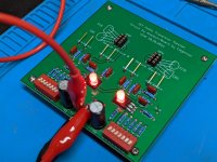
I just built the original ver2.0 board, and have a couple questions regarding my match accuracy %. I read earlier in the thread +-1mV is a good match but depends on the current, but I cannot find the equations to check.
My resistor matches; matched 4 wire with HP34401A
100R - 99.923/99.918 - 99.913/99.910
10K - 9.99599K/9.99583K - 9.99257K/9.99181K
Q1/Q2 - 2SA1381E / 2SC3503E
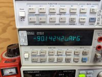
Example match on a pair of BC560C's with 5 minute timed Min/Max/Avg measurements after settling
-166.295 uV Min
-39.855 uV Max
-90.142 uV AVG
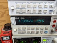
I switched the transistors around to check the balance
+69.626 uV min
+243.529 uV Max
+138.9626 uV AVG
I had dip switches 1 and 2 on which are 1k and 620R, and running +-11 vdc supply voltages.
Thanks
My resistor matches; matched 4 wire with HP34401A
100R - 99.923/99.918 - 99.913/99.910
10K - 9.99599K/9.99583K - 9.99257K/9.99181K
Q1/Q2 - 2SA1381E / 2SC3503E
Example match on a pair of BC560C's with 5 minute timed Min/Max/Avg measurements after settling
-166.295 uV Min
-39.855 uV Max
-90.142 uV AVG
I switched the transistors around to check the balance
+69.626 uV min
+243.529 uV Max
+138.9626 uV AVG
I had dip switches 1 and 2 on which are 1k and 620R, and running +-11 vdc supply voltages.
Thanks
Attachments
I had a quick look. The resistors below the 1K1 values (and it isn't critical) are to set the tail current. They will differ depending on the transistor E-B drop and the voltage reference used. Speaking of the voltage reference, A red LED (low efficiency) was chosen to partially compensate for the temperature coefficient of the E-B junction on the pass transistors. A voltage reference IC will not do that. Also, the 3mm LED originally used does fit in the mounting hole for a TO-126 transistor and we want to keep them at the same temperature so they compensate for each other. This combination may well be more stable than using a voltage reference, but it is up to you...
Lastly, for the terminals you must buy the more expensive ones from proper suppliers. The inexpensive terminals do not work well, and have poor contact after a short while. Inserting the leads in the cheap ones can be frustrating. so don't try and save a couple bucks here, you will only drive yourself crazy. Also the 100uF could be 10uF or even lower. These only serve to lower the circuit impedance at higher frequencies so things don't oscillate. 10 uF might be more effective, and again cheap capacitors won't work as well. You don't need the best, just reasonable good quality parts.
Thank you for your response!
I plan to go with the LEDs myself, but I figured I'd add the option and let people choose their components using the content of this thread (which you've just greatly added to) as a guide.
I did use the 10uF caps, it is working perfectly. I found by leaving one transistor in and exchanging just one that you will get a feel for which transistors will match and which won't by where they start out and how quickly the readings change. My first actual match was 30 uV. I got about 5 before that match that were at about 1.5mV. I decided that was close enough and removed both and soldered them in, LOL.
Going off previous posts, 100mv over the Collector resistors 1mv would be 1%, 200mv over the resistors 2mv would be 2% and so on, I could stand to be corrected but this is how I understand itI just built the original ver2.0 board, and have a couple questions regarding my match accuracy %. I read earlier in the thread +-1mV is a good match but depends on the current, but I cannot find the equations to check.
My resistor matches; matched 4 wire with HP34401A
100R - 99.923/99.918 - 99.913/99.910
10K - 9.99599K/9.99583K - 9.99257K/9.99181K
Q1/Q2 - 2SA1381E / 2SC3503E
Example match on a pair of BC560C's with 5 minute timed Min/Max/Avg measurements after settling
-166.295 uV Min
-39.855 uV Max
-90.142 uV AVG
I switched the transistors around to check the balance
+69.626 uV min
+243.529 uV Max
+138.9626 uV AVG
I had dip switches 1 and 2 on which are 1k and 620R, and running +-11 vdc supply voltages.
Thanks
I think its current dependent that is what I am trying to confirmGoing off previous posts, 100mv over the Collector resistors 1mv would be 1%, 200mv over the resistors 2mv would be 2% and so on, I could stand to be corrected but this is how I understand it
Hi,
It seems the Dropbox link doesn't work anymore. Can someone upload the files for this project again?
Br, Jonas
It seems the Dropbox link doesn't work anymore. Can someone upload the files for this project again?
Br, Jonas
That one works.
To figure out percentage match, simply read the current from the voltage drops across each 100R0 resistor and determine the current ratio. But basically the closer teh match is, the better. Better than 1 mV is pretty darned good and my matches are around or below that figure as acceptable. I use a 3 mA tail current as a good compromise between speed of settling and current level. Actual circuits are typically 0.5 to 1.5 mA per transistor.
-Chris
- Home
- Design & Build
- Equipment & Tools
- Matching transistors & measuring the results