Hi patriz,
If you use 0.1% resistors in the base and collector circuits, your offsets (error) will be minimal. You can reverse the transistor locations for a sanity check, but you will probably find any difference is well within experimental error. Temperature effects will be higher, so if you do this, you have got to let it settle at least 1/2 an hour.
If you use 0.1% resistors in the base and collector circuits, your offsets (error) will be minimal. You can reverse the transistor locations for a sanity check, but you will probably find any difference is well within experimental error. Temperature effects will be higher, so if you do this, you have got to let it settle at least 1/2 an hour.
Wow, @fireanimal this board! Superb!
My only suggestion, and it's a small one. On the silkscreen, you have depicted TO92 transistor outlines with pin locations in the most popular formats, labeled ECB and CBE, viewed from the face of the transistor. But there do exist BCE and EBC transistors, though they are less common.
My only suggestion, and it's a small one. On the silkscreen, you have depicted TO92 transistor outlines with pin locations in the most popular formats, labeled ECB and CBE, viewed from the face of the transistor. But there do exist BCE and EBC transistors, though they are less common.
Actually I just thought of something else, might be a good addition. 😃
For the collector test points, something that will stick up less than mini-grabbers, there are these cool multimeter probe-tip jacks from Cinch Connectivity.
105-0752-001 Red
105-0753-001 Black
There are more colors.

For the collector test points, something that will stick up less than mini-grabbers, there are these cool multimeter probe-tip jacks from Cinch Connectivity.
105-0752-001 Red
105-0753-001 Black
There are more colors.

Hey @fireanimal that's a beautiful looking board. I'm curious about the + and - LDOs on the board (LT3045 and LT3094) and what function they serve (regulation, duh?) What power input does the board expect? I see three banana jacks as power input. I'm guessing the power input is unregulated? I'd love to see a photo of the backside of the board (those lit leds have me intrigued). TIA
Hi, do you still have boards available?I do have extras, PM sent. Thanks!
I'm interested in one or two pieces.
Sorry I must of missed this before. The LDO's are just optional really. I use a Bench supply but I want to make sure the voltage is a stable as possible for accurate measurements thats why I included them. You can use the banana jacks or just solder wires to the pads or there is provision for spade connectors, whichever you chose. My original plan with the backside of the board for the LED's was to have no soldermask there so the light came through. But they masked it, so you must scrape off the soldermask with a sharp knife to allow the light to come through to the top. Optional and bling purpose only lol.Hey @fireanimal that's a beautiful looking board. I'm curious about the + and - LDOs on the board (LT3045 and LT3094) and what function they serve (regulation, duh?) What power input does the board expect? I see three banana jacks as power input. I'm guessing the power input is unregulated? I'd love to see a photo of the backside of the board (those lit leds have me intrigued). TIA
LOL!
Yup, and actually, unless you use a really terrible power supply it won't matter. But hey? Why not build them in?
Nothing wrong with bling! I found some banana jacks at Walmart (believe it or not). They arrived.
Yup, and actually, unless you use a really terrible power supply it won't matter. But hey? Why not build them in?
Nothing wrong with bling! I found some banana jacks at Walmart (believe it or not). They arrived.
Last edited:
Attached is the BOM with ID's for my version of the component matcher, and Mouser cart.
https://www.mouser.com/ProjectManager/ProjectDetail.aspx?AccessID=c4248c06ea
https://www.mouser.com/ProjectManager/ProjectDetail.aspx?AccessID=c4248c06ea
Attachments
Correct me if I am wrong, but you can use factory matched 0.1 % reistors, for example Vishay/Dale, when building the matcher? Or do you need to further match these resistors?
Hi NSP,
Yes, you can use the resistors out of the bag without matching them.
However, I have the ability to match the resistors very closely - so I do. That makes my matches closer with less error and I simply don't have to worry about this factor. By doing this, the resistors are probably matched within 0.01% starting with 0.1%. The absolute value isn't that close to the stated value, but the match is. That is what is the most important. You can measure the currents on the bases and collectors independently as well. The tail current would be the sum of the collector currents and base currents. For those measurements, the deviation for the stated value would be important unless you could measure that accurately and make a note of it. Most meters are not capable of measuring 0.1% or being stable enough for comparison type measurements over any period of time. If you have a higher end Fluke, HP / Agilent / Keysight or Keithley bench DVM (6.5 digit or better) you can probably do this. The HP 3457A is very good if you use the IEEE bus (it will give you 7 1/2 digit resolution then). You have to calculate your error budget for each range and function to be certain. That and how long it has been since last calibration because you may not even be in tolerance. I know HP through Keysight holds calibration wonderfully. Just keep the temperature constant and near the temperature it was calibrated at. My 34401A's have never been out of tolerance! Same for my 3457A and even 974A meters.
The beauty of this matcher is that it uses your meter as a null device. So the closer to 0.0mV you read - the better. Having said that, cheap meters do not read to even 1 mV with any accuracy, the thermocouple effects may well throw you off. Regardless, just go for minimum voltage difference.
-Chris
Hi Chris,
Thank you for your answer, great info! I have friends working in the industry and they have access to high end flukes. Maybe I can borrow one from them and at least try to match the resistors a little. Better than nothing i presume.
/Jonas
Thank you for your answer, great info! I have friends working in the industry and they have access to high end flukes. Maybe I can borrow one from them and at least try to match the resistors a little. Better than nothing i presume.
/Jonas
A friend has a Fluke 726, will this one be good enough to match the resistors? It seems to be pretty accurate, but I am not qualified enough to say. 🙂
Maybe this older thread might be useful: Resistor matching error starting with six 1% resistors
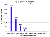
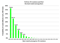
The somewhat surprising result from Monte Carlo analysis (100,000 trials) was that 55% of all trials found a resistor pair whose mismatch is less than 0.05% {blue histogram} . And that's from testing only six 1% resistors. If instead you purchase and test ten 1% resistors, >76% of the time you get a match better than 0.03% {green histogram}.
Assuming of course that your measuring instrument(s) are up to the task.
_
Attachments
One other thing to keep in mind when matching resistors is a 4-wire measurement is required, and you need to allow time for the resistor to settle, up to 5 minutes to get an accurate and stable reading.
I love HP 3458A meters! I used one, and they are a lab asset. You really would be hard pressed to use a better meter.
You don't always need a kelvin connection to get an accurate reading. For 100 R, yes you should for 0.1% tolerance. That's how my 3457A is normally left connected. The test current isn't high enough to cause self heating, but the DUT does need to return to room temperature. Depends on the temperature stability of the part.
The Fluke 726 is a multifunction process calibrator. It has current and voltage sources built in for common industrial transmission from transducers. It is pretty accurate, but the TUR is less than unity so you can't really measure values directly. It is more than good enough to match the resistors.
- Home
- Design & Build
- Equipment & Tools
- Matching transistors & measuring the results