Ricardo, here are the trimmers :
Bestellen Sie variable Trimmkondensatoren Trimmkondensator 300V 5pF bis 60pF Vishay MCO228180908003 online - versandkostenfrei ab 50 € Nettobestellwert.
Cool, they droped the price. This is the price for one and you have to by 5 minimum.
Thank you... I will try those.
I promissed the values for the shunt RIAA. They are derived by hard mathematics. After i calculated the values Frans has put them in the simulator and it worked.
I am sure Ricardo will come up with even more precise values.
Treble cap : 3.4483 nF
Series connection : 31.9 kOhm 10 nF
Bass resistor : 217.6 kOhm
I will study this 🙂
Silicon-carbite diodes in the PSU, R-Core transformers, i use Phoenix from Japan.
A source for those TX would be a pus also
Electrolytics : Mundorf silver-gold 4 pole.
Maybe you should also consider the Jensen four pole.... I found those really good in the trebble
I added your corrections, please tell me if I missed something.
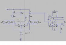
Nevertheless simulated model seems not to work still.
Any thought?
Add a capacitor, say 100u to 1m, in parallel to R11, then add a few base stoppers to the transistors, say 50 to 100 Ohm. Anyway that is what I would do 🙂
Add a capacitor, say 100u to 1m, in parallel to R11, then add a few base stoppers to the transistors, say 50 to 100 Ohm. Anyway that is what I would do 🙂
yes agree with you, but this won't change the fact that circuit seems to not simulate right or better it doesn't operate properly.
any hint?
Maybe I am using the wrong model for the differential opamp?
Well, after some hard mathI promissed the values for the shunt RIAA. They are derived by hard mathematics. After i calculated the values Frans has put them in the simulator and it worked.
I am sure Ricardo will come up with even more precise values.
Treble cap : 3.4483 nF
Series connection : 31.9 kOhm 10 nF
Bass resistor : 217.6 kOhm
 , I found that your values would be almost perfect ... as a matter of fact, much more linear aproximation than in the original paradise.
But I still believe the outcome would tend to Nasal sound with too much attack ... meaning, slight lack of bass and quite snappy.
I admit that your bass resistor is ok so I would suggest:
Trebble cap: 0,003447 (3.447nF)
Mid freq series: 31.64k ohm and 10nF
Bass resistor: 217.6 k ohm
Off course these values are much simpler to get here because we do not need to care about the second stage miller (depending on gain) of second stage.
Anyway, I would like to have Stefano's input because I know he is quite good at this also.
how about input impedance of the 1632..?? That will impact the working condition for the input-stage
Yes... off course, but I admit Joachim took that into consideration when choosing the bass resistor 217.6kr
The Panasonic material should be available from PCB makers that do RF stuff.
There is also Material from Rogers and Isola but Bob Cordell posted that the Panasonic is even better.
We have silver plating on the Pardise boards because we wanted to avoid any magnetic material in the plating. Gold plaiting is usually done with nickel first and then gold on top.
The problem with the Paradise boards is that the silver easy oxidizes.
It is not a tragedy but after a while it does not look as pretty any more.
Paradise PBC tracks, according to pictures, are protected by solder resist. What is the purpose of silver plating? Bare copper is better solution , or even solder plated bare FR4 PCB in Audio Research fashion.They believe that solder resist degrades sound quality.
Last edited:
Stefano, post 402 is not right ether. Put the bass resistors R9, R10 PARALLEL to C1, C3.
Thanks Ricardo for your little tuning. As i said i came up with his numbers by mathematics. The error must be small.
I have Baxandalls formulars.
Thanks Ricardo for your little tuning. As i said i came up with his numbers by mathematics. The error must be small.
I have Baxandalls formulars.
MiiB, i build many shunt RIAA stages with the OPA1632 and with my values the result was precise to plus-minus 0.1dB so input impedance of the OPA1632 is a non issue.
Here is the OPA1632 :
http://www.ti.com/lit/ds/symlink/opa1632.pdf
Input impedance on each input is 34MOhm and 4pF.
http://www.ti.com/lit/ds/symlink/opa1632.pdf
Input impedance on each input is 34MOhm and 4pF.
Under " Network " you can find various choices of Panasonic RF PCB materials.
Application|Panasonic Corporation
I think Bob Cordell mentioned Megtron.
DF of 0.01 at 1GHz is not bad.
Application|Panasonic Corporation
I think Bob Cordell mentioned Megtron.
DF of 0.01 at 1GHz is not bad.
Paradise PBC tracks, according to pictures, are protected by solder resist. What is the purpose of silver plating? Bare copper is better solution , or even solder plated bare FR4 PCB in Audio Research fashion.They believe that solder resist degrades sound quality.
True. Solder Mask will prevent silver from tarnishing.
The silver bath will help conductivity IMHO.
Under " Network " you can find various choices of Panasonic RF PCB materials.
Application|Panasonic Corporation
I think Bob Cordell mentioned Megtron.
DF of 0.01 at 1GHz is not bad.
that is an impressive material, let me check where it can had and at what price.
can't you split the circuit in order to get the front end working..??
Let me try first to change what Joachim suggested and then see if splitting solves.
It might be the model for the op amp I am using.
Stefoanoo, have you seen my comment how the RIAA components have to be arranged ?
The structure for shunt feedback is basically the same that we use in the Paradise.
Shunt feedback RIAA is rare so i can understand that you do not find the solution immediately.
The structure for shunt feedback is basically the same that we use in the Paradise.
Shunt feedback RIAA is rare so i can understand that you do not find the solution immediately.
Here you find some shunt RIIAs and other interesting information :
http://www.angelfire.com/sd/paulkemble/sound4.html
Shunt is more popular in England. Lindsley-Hood was always an advocate.
http://www.angelfire.com/sd/paulkemble/sound4.html
Shunt is more popular in England. Lindsley-Hood was always an advocate.
Here are some JLH designs :
A Paul Kemble web page - John Linsley Hood preamp designs.
The Hart JLH 1450 kit is a good example of a shunt RIAA.
It is a bit outdated but it shows the principle.
A Paul Kemble web page - John Linsley Hood preamp designs.
The Hart JLH 1450 kit is a good example of a shunt RIAA.
It is a bit outdated but it shows the principle.
Stefano, when you go to this page :
Audio - Audio Operational Amplifier - OPA1632 - TI.com
You see on the right side simulation models of the OPA1632, but this is for Tina and not for
LT Spice.
Audio - Audio Operational Amplifier - OPA1632 - TI.com
You see on the right side simulation models of the OPA1632, but this is for Tina and not for
LT Spice.
- Status
- Not open for further replies.
- Home
- Source & Line
- Analogue Source
- Masterpiece