Wow, I didn't know the price was up that much, makes my little speakers more valuable 😀
I invested in them before they went up. I have 22 of them.
dave
Member
Joined 2009
Paid Member
At some point likely. We were considering doing them up as a fill-in for the old FF85, but the price jump and the new FF85 killed that idea.
We are likey going to build an experimental array
dave
We are likey going to build an experimental array
dave
Member
Joined 2009
Paid Member
Well it looks as if prices are reasonable on these drivers (e.g. Madisound $39.90). I may build another pair.
I thought I'd update this thread with some more data.
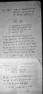
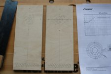
First image are the calculations I used for the horn-shaped slot port.
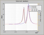
Second image shows the simulated impedance curves for a straight bass-reflex design. Note the two peaks, typical of a BR design the interaction of the driver and box, they are roughly the same height. The simulated resonance peaks are at 50Hz and 140Hz.
Third image shows the measured impedance curves. I used my DIY TGM3 amplifier (solid state) with a resistor in series with the ground wire and a DMM across it to measure the rms voltage and used this to calcite the current and along with the signal amplitude the impedance of the speaker. I used a sine wave generator signal source. The vertical axis is not calibrated in Ohms but it is linear. The measured resonance peaks are at 50Hz and 140Hz, matching the BR simulation. BUT note that the left hand peak is much smaller - a result of the damping provided by the Onken style ports.
I thought I'd update this thread with some more data.
First image are the calculations I used for the horn-shaped slot port.
Second image shows the simulated impedance curves for a straight bass-reflex design. Note the two peaks, typical of a BR design the interaction of the driver and box, they are roughly the same height. The simulated resonance peaks are at 50Hz and 140Hz.
Third image shows the measured impedance curves. I used my DIY TGM3 amplifier (solid state) with a resistor in series with the ground wire and a DMM across it to measure the rms voltage and used this to calcite the current and along with the signal amplitude the impedance of the speaker. I used a sine wave generator signal source. The vertical axis is not calibrated in Ohms but it is linear. The measured resonance peaks are at 50Hz and 140Hz, matching the BR simulation. BUT note that the left hand peak is much smaller - a result of the damping provided by the Onken style ports.
Attachments

I realised now that tomorrow will be a boring day with nothing to do. Why not use some of the scraps of 12mm and 22mm particle board in my garage and build a pair of Martellos? This time I will focus on making them look as good as possible and if they turn out well I'll buy drivers, binding posts and damping material 🙂
Should be able to build a pair in just a few hours 🙂
Should be able to build a pair in just a few hours 🙂
Must be nice not to have an infinite list of honeydos. Make hay while the sun shines. You're time is coming🙂
Most pieces cut 🙂
Took more time than expected because my dad had "stolen" all the tools so all I had was a handsaw... And when I came to the point of putting the pieces together I found out that I had no glue and no wooden plugs :S
Took more time than expected because my dad had "stolen" all the tools so all I had was a handsaw... And when I came to the point of putting the pieces together I found out that I had no glue and no wooden plugs :S
Member
Joined 2009
Paid Member
I realised now that tomorrow will be a boring day with nothing to do. Why not use some of the scraps of 12mm and 22mm particle board in my garage and build a pair of Martellos?
over here it's a long weekend, we get Monday off - the country celebrates Queen Victoria's birthday and we do that with horizon-to-horizon blue skies, 30 deg.C and a cold beer or two 🙂
Good luck with the build - but it's handy having the drivers to hand in order to size the opening / clearance whilst still keeping enough wood for the mounting screws to bite into - it's a bit of a balancing act so be careful with that.
Must be nice not to have an infinite list of honeydos. Make hay while the sun shines. You're time is coming🙂
and that's the other balancing act !
Last edited:
So should we, back in the old country. However, we do have Her Majesty's Diamond Jubilee celebrations in a couple of weeks.
over here it's a long weekend, we get Monday off - the country celebrates Queen Victoria's birthday and we do that with horizon-to-horizon blue skies, 30 deg.C and a cold beer or two 🙂
Good luck with the build - but it's handy having the drivers to hand in order to size the opening / clearance whilst still keeping enough wood for the mounting screws to bite into - it's a bit of a balancing act so be careful with that.
We also had long weekend, but last thursday and friday was "free" for me. Unfortunately I had to help dad clear some huge (yes, huge!) fallen trees at our summer house. About +10c and rain those two days...
I'll be careful when doing the baffles, to make sure I got enough wood for the screws. Wont be easy but with some precision work it should work 🙂
Was +5c and rain today... Will be warmer tomorrow it seems.
Took more time than expected because my dad had "stolen" all the tools so all I had was a handsaw...
Hmmm, dad took the tools .....
Sounds like he's gotten his revenge.
Hmmm, dad took the tools .....
Sounds like he's gotten his revenge.
Nah, he was just doing some carpentry work for a friend during the day. And I thought he had taken the jigsaw too (which I needed) but when he came home he told me he didn't have and it turned out that I didn't look enough for it because it was in the "workshop".
Still haven't found time to buy more glue and wooden plugs. We'll see when I get time.
Member
Joined 2009
Paid Member
I decided to build another pair of these !
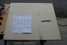
I took more pictures this time.
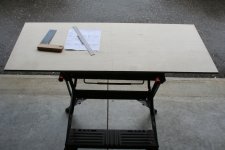
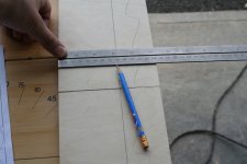
1 - Started off with new piece of 12mm Russian Birch plywood. Workbench at garage entrance (out of the rain)
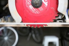
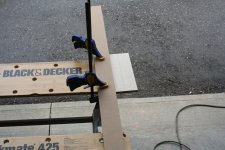
2 - I have no table saw, so the cutting will be with hand-held circular saw with a nice large-tooth high quality blade. First job to measure the blade offset so I know where to place a guide piece when cutting
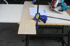
3 - I clamp a guide piece of scrap wood across the work piece to guide the base-plate of the saw. The clamps hold everything to the workbench.
I took more pictures this time.
1 - Started off with new piece of 12mm Russian Birch plywood. Workbench at garage entrance (out of the rain)
2 - I have no table saw, so the cutting will be with hand-held circular saw with a nice large-tooth high quality blade. First job to measure the blade offset so I know where to place a guide piece when cutting
3 - I clamp a guide piece of scrap wood across the work piece to guide the base-plate of the saw. The clamps hold everything to the workbench.
Attachments

Member
Joined 2009
Paid Member
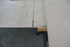
4 - then I set the blade depth so that it cuts nicely through the workpiece but no further.
5 - using the guide piece ensures the cut follows the right line which was measured to reduce the 2ft x 4ft starting sheet to a pair of 2ft x 2ft pieces. I need only one of these for a pair of Martello's
6 - next I mark up the 2ft x 2ft piece into three, following the drawing (posted earlier). the wide pieces are measured to a width of 25.5cm from each edge of the workpiece, leaving a centre strip that will be cut further.
Attachments
Member
Joined 2009
Paid Member
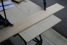
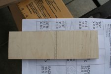
7 - the first two cuts are completed, ready to me marked up
8 - I've placed the two 25.5cm wide pieces side by side so I can cut them both at the same time. using the guide piece I measure and cut the fronts, the backs and the sides of the speakers
9 - then with what is left from the 25.5cm wide pieces I measure up to cut out a top, a btw and two port pieces
Attachments

Member
Joined 2009
Paid Member
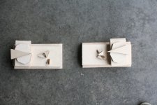
10 - for the smaller pieces I remove the centre plank of the workbench to make clamping easier
11 - the small pieces get measured up
12 - this piece will provide a bottom piece and port piece, the shaded piece between them will be scrap
11 - the small pieces get measured up
12 - this piece will provide a bottom piece and port piece, the shaded piece between them will be scrap
Attachments
Member
Joined 2009
Paid Member
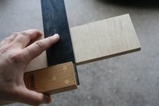
13 - the small pieces are difficult to clamp with a guide piece, so these will be clamped and cut free-hand
14 - and the scrap piece is of uniform thickness so the free-hand cutting was pretty accurate
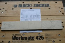
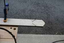
15 - next up is the centre piece from the initial 2ft x 2ft work piece. It's marked up for the port triangles, another top and bottom piece, and the braces
14 - and the scrap piece is of uniform thickness so the free-hand cutting was pretty accurate
15 - next up is the centre piece from the initial 2ft x 2ft work piece. It's marked up for the port triangles, another top and bottom piece, and the braces
Attachments
Member
Joined 2009
Paid Member
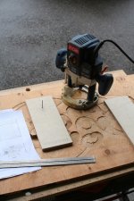
16 - and the cutting begins
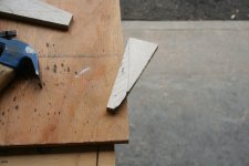
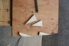
17 - the 'wasted' triangles from cutting the braces should be kept, they will make good reinforcement pieces that can be glued into inside corners of the boxes before they are closed
18 - the port triangles are hard to clamp for cutting when using a circular saw because the offset of the blade from the edge of the base of the saw is too large to allow room for the clamp. I nailed them to a piece of scrap wood instead.
Attachments
Member
Joined 2009
Paid Member
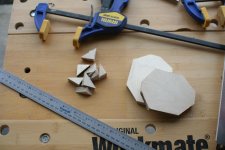
19 - the port triangles are now cut
20 - which completes the cutting ! phew !
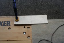
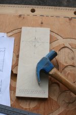
21 - next step is to mark up the front pieces for routing of the port slot and the driver opening
20 - which completes the cutting ! phew !
21 - next step is to mark up the front pieces for routing of the port slot and the driver opening
Attachments
Member
Joined 2009
Paid Member
22 - again clamping is not possible as the router needs lots of free space to swing around. So I nailed the front piece to some scrap wood, nailing through where the driver opening will be as this will be material later removed.
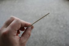
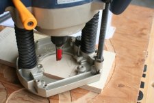
23 - a large nail is placed at the centre of the speaker opening to act as a pivot point for the router
24 - conveniently my router has a hole in the base for the nail that positions the cutting piece just the right radius for the driver opening. Otherwise I would have screwed a think piece of material to the base of the router with a hole for the nail at the appropriate distance from the cutting piece. This is a high quality cutting piece.
Attachments
- Home
- Loudspeakers
- Full Range
- Martello enclosure for FR88EX