Another question and by the way, it is just a black wire, no yellow stripe. It must appear that way due to reflection. You say I can check the primary winding in the same manner, but those 3 wires are all that comes from the transformer. So how does that work?
i think i figured it out. I connected the leads from the meter to the input wires (blue, brown) and got a 2.0 reading, double the value of the secondary output wires. Is that what we were looking for? And I did do a reading on the secondary right before I did the primary and they both settled at 1.0.
Last edited:
again i'm not there to observe what your doing but if your reporting your findings correctly both the primary and secondary windings are ok.
do you have any clip leads?
do you have any clip leads?
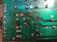
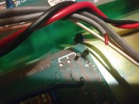
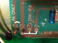
hERE ARE SOME UPDATED PICTURES OF WHAT i'VE BEEN DOING. These funky fuse holders were wired in there pretty good and took a while to free them up and off as did the old rectifier pins. Unfortunately a wire that had little play came undone at the corner of the board, that is a red wire with gray insulation you will see in one of the pics. Also, I hope I didn't fry the board to badly. You tell me. Then you will see the upside of the board with the holes for the bridge rectifier cleared out and ready for the new one. in the last picture you will see a sticker that says 7 amp pico fuses f1 and f2. I got a new phone with a better camera. I have to look for the clips.I .can get some at the electronics store if I have to.
Attachments
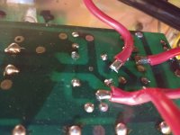
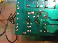

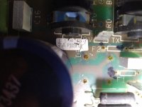
well there is some damage to the foil on the pcb which may require some jumpers to be added.
do you have a desolder pump or some desoldering braid?
that gray wire is a shielded lead so there's a gnd connection and the inner red conductor to be redone/reattached.
do you have a desolder pump or some desoldering braid?
that gray wire is a shielded lead so there's a gnd connection and the inner red conductor to be redone/reattached.
yes, I have a solder sucker. I was wondering if I should have broken that out. I think my mistake was using the soldering gun instead of a pencil type. The guns tend to get hot and have a large heat radius instead of directing it to one place. Soldering is not my forte' for sure. That is actually one of my better attempts at it. What is next?
I figure I'll wait till I get the fuses and rectifier put in before I reattach the red wire. some of the black on the board is my notation that no one else can read. So the sticker says 7 amp pico's and I got 10 amp pico's, will that pose a problem? and whoever put those fusible links in was using 6 amp slow blows. Aren't the pico's fast blow? What could that have screwed up?
I figure I'll wait till I get the fuses and rectifier put in before I reattach the red wire. some of the black on the board is my notation that no one else can read. So the sticker says 7 amp pico's and I got 10 amp pico's, will that pose a problem? and whoever put those fusible links in was using 6 amp slow blows. Aren't the pico's fast blow? What could that have screwed up?
Last edited:
when it comes to the fuse rating and the difference between fast and slow blow fuses an understanding of peak and RMS conditions is necessary so a little homework Peak vs. Average vs. RMS Voltage
whomever was in there last was trying to find the mean fuse value that would offer protection despite a potential fault condition but that's a speculation we'll leave aside for the moment.
testing the transformer secondary voltage is what i would do along with assessing the output transistors further.
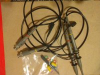
RMS=continuous, maximum safe operating wattage? I do have some clip test leads but they go to that digital oscilloscope that I don't know how to use yet. They have BNC ,connectors
well as we are going to be checking things that could have shock potential it's imperative you have the means to connect your multimeter via clip leads, no hand holding of probes allowed....safety is paramount.
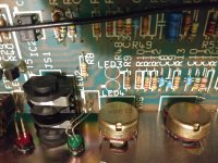
1 are those the right kind? 2 I soldered the switch in. 3 I noticed LED 3 AND 4 are missing, is this ok? 4 some other missing or empty holes
I think its time to learn how to use that scope, thats what those leads are from
'
I think its time to learn how to use that scope, thats what those leads are from
'
Attachments
Last edited:
1 are what the right kind? those scope probes? no sorry
2 O.K. not the prettiest work and without the mechanical support of having the wire through the hole of the switch tab let's hope there's no cold solder joints....
3 what does the board look like on the foil side?does it look like it's been worked on? this pcb could be used for several preamp versions and for this model they are not used/needed. i did a quick look at the schematic and am not seeing them, i'll look further later.
4 same as 3
I've got to go get some clip leads for the meter. I haven't had time as we had an urgent matter come with a clogged septic system. A lot of nasty work. Holiday today, so shop will be closed. Will post as soon as I get them. What test for the output transistors should I be doind and what values should I expect?
Should I solder in the fuses and bridge rectifier or hold off on that nor?
Should I solder in the fuses and bridge rectifier or hold off on that nor?
Last edited:
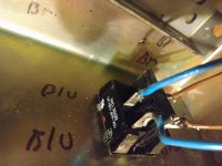
I want to mske sure the wiring is vorrect on the DBT before I use it. !. White wire comes in from ac plug, goes to outlet on side where jumper is broken terminal 1, red wire from terminal 2 goes to on off switch wire 1, wire 2 from switch goes back out to ac plug completing the circuit.
\Ohm and my multimeter took a turn for the worst and I want to get a good one this time. I had a fluke at one time and I was checking some out but they have so many. I could use a recommendation.
\Ohm and my multimeter took a turn for the worst and I want to get a good one this time. I had a fluke at one time and I was checking some out but they have so many. I could use a recommendation.
Last edited:
can you draw a complete schematic of your DBT? the most important thing is that the light bulb be in series with the load, including the switch is a good idea but is not essential.
when it comes to meters there are so many choices available and budget will ultimately be a factor in final choice, my choice would guided by spec's such as impedance (ohm's/volt rating) number of functions (many include things like capacitor test function but are limited in range) so rather then put forward a recommendation of brand or price category or fancy features you may never need looking for something that has the basic volts (AC, DC) ohms (wide range) and current (to 10 amps as well low milli-amps range) and from a reputable brand should get you a good/decent meter for your purposes. i'll gladly review any choices you make before purchase.
when it comes to meters there are so many choices available and budget will ultimately be a factor in final choice, my choice would guided by spec's such as impedance (ohm's/volt rating) number of functions (many include things like capacitor test function but are limited in range) so rather then put forward a recommendation of brand or price category or fancy features you may never need looking for something that has the basic volts (AC, DC) ohms (wide range) and current (to 10 amps as well low milli-amps range) and from a reputable brand should get you a good/decent meter for your purposes. i'll gladly review any choices you make before purchase.
What I was asking is among the Fluke .keeps which one will perform the duties needed for what is to be tested , I'd rather get one that covers everything that I will need, instead of coming up short.
So, I'm looking at the Fluke 115, 175 or the 177 with back light. Will any of those do? Please don't be wishy washy, which would you get? Or not get? Thanks.
In the back of my head, Fahey's comment is renting space and I'm hoping we don't make or surpass the 300 post's mark he mentioned and if it does I want or would like some fruit to bear at the end of it all. It is taking a long time because I have to work at making $$ at one thing or another on most days. I have been busy and have work lined up in my landscaping and yard work this time of year and I got to take it as it comes and do my required work here at the ranch as well as hauling in my accumulated non ferrous scrap metal. This is a non-essential back seat hobby for now. No rush.
In the back of my head, Fahey's comment is renting space and I'm hoping we don't make or surpass the 300 post's mark he mentioned and if it does I want or would like some fruit to bear at the end of it all. It is taking a long time because I have to work at making $$ at one thing or another on most days. I have been busy and have work lined up in my landscaping and yard work this time of year and I got to take it as it comes and do my required work here at the ranch as well as hauling in my accumulated non ferrous scrap metal. This is a non-essential back seat hobby for now. No rush.
Fluke 115 True RMS Digital Multimeter-
Downloads: Datasheet Manual
Fluke 115 True RMS Digital Multimeter
Model: 115 | Order No: 115/EFSP | UPC: 95969324182
4 Reviews
Ideal for electrical and electronic testing applications, this True RMS meter also comes equipped with simple, one-handed operation and compact design. Additionally, it measures True RMS voltage and current with 6000 count resolution as well as resistance, continuity, frequency, and capacitance.
Sale Price $184.49 USD
Regular Price $204.99 USD
Availability 1 Week
Quantity
1
Fluke 175 True RMS Digital Multimeter-
Downloads: Datasheet Manual
Fluke 175 True RMS Digital Multimeter
Model: 175 | Order No: 175/EFSP | UPC: 95969095181
1 Reviews
Provides all the general-purpose features needed by professional technicians, which makes this True RMS digital multimeter ideal for identifying basic troubleshooting measurements such as frequency, capacitance, resistance, continuity, and diode. Additionally, it enables closed-case calibration through the front panel.
Sale Price $287.99 USD
Regular Price $319.99 USD
Availability 5 Days
Quantity
1
Fluke 177 True RMS Digital Multimeter with backlight-
Downloads: Datasheet Manual
Fluke 177 True RMS Digital Multimeter with backlight
Model: 177 | Order No: 177/EFSP | UPC: 95969095198
Be the first to review this product
Troubleshoot and repair problems in electrical and electronic systems. Additionally, this meter is ideal for professional technicians due to its precision, reliability, and ease of use, along with a CAT IV 600 V/ CAT III 1000V rating.
Sale Price $314.99 USD
Regular Price $349.99 USD
Availability 5 Days
Quantity
1
Downloads: Datasheet Manual
Fluke 115 True RMS Digital Multimeter
Model: 115 | Order No: 115/EFSP | UPC: 95969324182
4 Reviews
Ideal for electrical and electronic testing applications, this True RMS meter also comes equipped with simple, one-handed operation and compact design. Additionally, it measures True RMS voltage and current with 6000 count resolution as well as resistance, continuity, frequency, and capacitance.
Sale Price $184.49 USD
Regular Price $204.99 USD
Availability 1 Week
Quantity
1
Fluke 175 True RMS Digital Multimeter-
Downloads: Datasheet Manual
Fluke 175 True RMS Digital Multimeter
Model: 175 | Order No: 175/EFSP | UPC: 95969095181
1 Reviews
Provides all the general-purpose features needed by professional technicians, which makes this True RMS digital multimeter ideal for identifying basic troubleshooting measurements such as frequency, capacitance, resistance, continuity, and diode. Additionally, it enables closed-case calibration through the front panel.
Sale Price $287.99 USD
Regular Price $319.99 USD
Availability 5 Days
Quantity
1
Fluke 177 True RMS Digital Multimeter with backlight-
Downloads: Datasheet Manual
Fluke 177 True RMS Digital Multimeter with backlight
Model: 177 | Order No: 177/EFSP | UPC: 95969095198
Be the first to review this product
Troubleshoot and repair problems in electrical and electronic systems. Additionally, this meter is ideal for professional technicians due to its precision, reliability, and ease of use, along with a CAT IV 600 V/ CAT III 1000V rating.
Sale Price $314.99 USD
Regular Price $349.99 USD
Availability 5 Days
Quantity
1
- Home
- Live Sound
- Instruments and Amps
- Marshall 3315 missing parts???