Exactly. Thank you. Did you simulate it and you got that 2Meg?
Those resistors are soldered vertically in very tight place so I will not touch it for now. But when I am replacing the caps on this left amp I will do it.
Those resistors are soldered vertically in very tight place so I will not touch it for now. But when I am replacing the caps on this left amp I will do it.
Exactly. Thank you. Did you simulate it and you got that 2Meg?
Those resistors are soldered vertically in very tight place so I will not touch it for now. But when I am replacing the caps on this left amp I will do it.
You asked for a sim, here it is. The amp used now draws 3.3uA Ibias, and input resistors are resp 100K and 95K3.
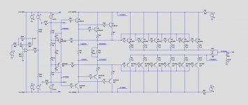
So use this image fur future voltage references.
Hans
Attachments
Hans,
Thanks a lot for another simulation.
I have good news. The voltage regulator works now perfectly after soldering the new Q31 (MJE15030). I connected only the regulator part, not Vcc unreg and verified the operation.
Shall I connect again the lamps between the VCC unreg lines and try to make the 50V voltage drop?
Hans,
Thanks a lot for another simulation.
I have good news. The voltage regulator works now perfectly after soldering the new Q31 (MJE15030). I connected only the regulator part, not Vcc unreg and verified the operation.
Shall I connect again the lamps between the VCC unreg lines and try to make the 50V voltage drop?
Yes, the lamps are your safeguard.
With 50V voltage drop, all voltages should be as in posting #242.
Hans
When that’s all o.k. I’m ready to tell the next step.
If voltages are not o.k. and turning the pot has no effect, measure all the voltages at the spots shown in blue in #242 and measure the current directly between WH.1 and WH.5 with your multimeter.
Hans
If voltages are not o.k. and turning the pot has no effect, measure all the voltages at the spots shown in blue in #242 and measure the current directly between WH.1 and WH.5 with your multimeter.
Hans
I have again the problem that I cannot adjust the voltage drop over the lamps. Now the pot is in the safest position(fully open) and the voltage drop is already 85V.
As far as I know voltage drop should be now close to zero and by turning the pot it should increase. Right?
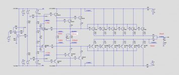
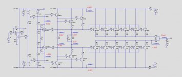
Attached are some important measurements.
As far as I know voltage drop should be now close to zero and by turning the pot it should increase. Right?
Attached are some important measurements.
Attachments
I have again the problem that I cannot adjust the voltage drop over the lamps. Now the pot is in the safest position(fully open) and the voltage drop is already 85V.
As far as I know voltage drop should be now close to zero and by turning the pot it should increase. Right?
Attached are some important measurements.
This is great with all the voltages. Now I can start to replicate your results trying to find the cause.
Give me an hour or so.
At least the 16mA is perfect.
One question: Was the OL-2 board connected or not in your measurements.
Hans
OL-2 is connected and everything else except the input cable from OL-2 to the mainboard.
I think I have found the problem. I have measured voltages over all the 0.22R resistors and here are the results:
mV mV
+ -
3.42 3.29
3.08 3.83
3.58 3.51
3.76 3.45
0 0.2
3.58 3.82
The collector voltages are 0.95/-0.85 respectively.
I think I have found the problem. I have measured voltages over all the 0.22R resistors and here are the results:
mV mV
+ -
3.42 3.29
3.08 3.83
3.58 3.51
3.76 3.45
0 0.2
3.58 3.82
The collector voltages are 0.95/-0.85 respectively.
You may have have found a problem, but I'm not sure if this is "the" problem.
When dividing all voltages through 0.22 and adding them, the positive side gives 79mA and the negative side 82mA, roughly the same.
The voltage over R20 is 10mV, so divided by 0.1 Ohm is 100mA.
So I still miss some 20mA, exactly what one complementary pair should have added.
Are you sure about the 0mV and the 0.2mV.
Bet even when there is 0mV on a 0.22Ohm resistor, it only means that this transistor is not conducting because the 0.22Ohm resistor in disconnected or the 10Ohm Base resistor is not connected.
You could check this with the power off.
But I see no cause of the problem real problem in this.
Now I would like you to ask you to do the following:
Make 2 pictures exactly as you did with the voltages in red but now
1) with the pot in the minimum position , and
2) with the pot in the max position.
Hans
What you have is very strange.
Is it possible to take out one side of R45, 158Ohm.
This resistor momentarily prevents Q29,30,41 and 42 from conducting.
Again all voltages like in the last posting.
Hans
Is it possible to take out one side of R45, 158Ohm.
This resistor momentarily prevents Q29,30,41 and 42 from conducting.
Again all voltages like in the last posting.
Hans
I may have found the cause of your problem.
You were right after all with the 0.22Ohm resistors having no current.
These particular power transistors must have a Collector-Base short, while the emitters are not conducting.
Either this is a short circuit on your PCB, the most likely cause because the problem is intermittent, or the transistors are broken.
To get this confirmed, take out the 10 Ohm base resistor of these transistors.
If you haven't taken our R45, just leave it in place.
Hans

It is probably simply possible to find those Base Collector short circuits with the power switched off by measuring with your mulltimeter.
Hans
Hans
I have found the shorts and I will desolder those two transistors tomorrow at my work. I hope it is only short and the transistors are ok. Thank you so much again.
I desoldered the shorted transistors and found them broken.😡
So, I need one pair of MJ15024/MJ15025. Any suggestions from where?
Sould them be matched? from ebay? Farnell? old Motorola or new?
So, I need one pair of MJ15024/MJ15025. Any suggestions from where?
Sould them be matched? from ebay? Farnell? old Motorola or new?
I have also option to buy complete old set with five pairs color coded transistors. Those should be matched by manufacturer.
I have also option to buy complete old set with five pairs color coded transistors. Those should be matched by manufacturer.
Sorry to hear they are broken.
I would replace them by the ON Semiconductor MJ15024/15025 costing ca. 7,-Euro each from Farnell.
Matching seems nice, but not really necessary with this high idle current and large base resistors.
After having replaced them, you should keep using the lamps, since we still have not solved the problem.
Everything worked fine with lamps two weeks ago, but when you removed the lamps, disaster stroke and killed your output transistors.
So we still have to try finding what was causing this all.
What's strange is that in no way the original problem could be replicated: Output ca. 3 Volt and -85Volt on WH.5.
So lamps are mandatory in further fault finding.
It must be a bad soldering, a hair line crack or something like that.
So when ordering output transistors, you could also order a freezer spray aerosol to do a stress test.
Hans
- Home
- Amplifiers
- Solid State
- Mark Levinson No23 repair help