I'm just wondering that how can it still generate the 12V for the balanced circuits...
R113 is probably mounted on a heatsink, but is has to dissipate 2.3 Watt now instead of 1.2 Watt at 83 Volt +Vcc Reg.
So don't expose this to long to 111 Volt.
Hans
OK. Do you know if there is a good webshop in the Netherlands? Normally I have ordered from Ebay but it takes long time to deliver.
OK. Do you know if there is a good webshop in the Netherlands? Normally I have ordered from Ebay but it takes long time to deliver.
Farnell, next day delivery
Conclusion was that Diode is ok but the MJE is broken. I already ordered 2 pcs from Farnell. I hope that is the only broken one.
In the meantime can I somehow dig into the shut down problem?
In the meantime can I somehow dig into the shut down problem?
I checked the voltage over R20 from the left amp (well warmed) and it is 22mV.
Is it too low?
And there is no shut down problem, so it have to be in right amp.
Is it too low?
And there is no shut down problem, so it have to be in right amp.
Did you completely shut off the right amp ?
It is not wise to expose it to 111 Volt, that will cause more damage.
1) 22mV on R20 of the left amp is a bit low, should be 27.5mV after warming up. You know how to adjust it.
2) You could check again the shut down circuit on the right amp without power on.
Disconnect P332 and measure the cable from here the resistance to gnd.
This should be practically zero ohm.
When you interupt the line through the temp sensors, preferably WH.11, the line should go from zero ohm to infinity.
3) Did you find the User Manual with the value of the fuses ?
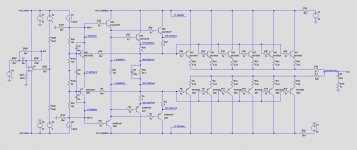
4) I have made a new simulation with the lamps in the lines, here visible as R14 and R22, both having 50V voltage drop.
Plse make a copy of this circuit diagram, and use it to report the voltages to me on those places where voltages are shown (14 different values) after you have repaired the Vcc Reg.
That will save you and me a lot of time.
Hans
It is not wise to expose it to 111 Volt, that will cause more damage.
1) 22mV on R20 of the left amp is a bit low, should be 27.5mV after warming up. You know how to adjust it.
2) You could check again the shut down circuit on the right amp without power on.
Disconnect P332 and measure the cable from here the resistance to gnd.
This should be practically zero ohm.
When you interupt the line through the temp sensors, preferably WH.11, the line should go from zero ohm to infinity.
3) Did you find the User Manual with the value of the fuses ?
4) I have made a new simulation with the lamps in the lines, here visible as R14 and R22, both having 50V voltage drop.
Plse make a copy of this circuit diagram, and use it to report the voltages to me on those places where voltages are shown (14 different values) after you have repaired the Vcc Reg.
That will save you and me a lot of time.
Hans
Attachments
Last edited:
Thanks again for the schematic. That is good idea to use reporting the numbers.
I disconnected the right amp when measuring the left one.
I could not find my own 23 manual but 23.5(basically same amp) fuse size is 8A so I think I have the right size.
This left channel biasing is funny because I need to increase it every time I check. Hopefully it is soon stabilized.
I disconnected the right amp when measuring the left one.
I could not find my own 23 manual but 23.5(basically same amp) fuse size is 8A so I think I have the right size.
This left channel biasing is funny because I need to increase it every time I check. Hopefully it is soon stabilized.
I have another question; my left amp is not connected(No Vcc unreg, Vcc reg or OL-2 connected.) but I connected the P332 cable. I cannot turn the amp on because it will immediately shut down. Is it working right?
What is turning the amp off in this case?
What is turning the amp off in this case?
I have another question; my left amp is not connected(No Vcc unreg, Vcc reg or OL-2 connected.) but I connected the P332 cable. I cannot turn the amp on because it will immediately shut down. Is it working right?
What is turning the amp off in this case?
That's O.k. because I gave you the wrong number, P332 belongs to the right channel 😀 I thought your right channel was defective.
Take off P333, that's the left channel.
Hans
Now I'm really confused.
Taking off P332 or P333 should never result in switching off the Amp no matter right or left channel.
If it does, the circuit diagram you gave me does not match your amp.
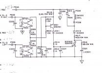
See image below.
A current has to flow through the diode of the 4N33 opto coupler to activate the triac that energises shut off relay SW300.
No connection, means no current can flow.
So with both P332 and P333 detached from this circuit, you completely disable the protection circuit on OL-2 for both amps.
But only when you have this circuit diagram.
Hans
Taking off P332 or P333 should never result in switching off the Amp no matter right or left channel.
If it does, the circuit diagram you gave me does not match your amp.
See image below.
A current has to flow through the diode of the 4N33 opto coupler to activate the triac that energises shut off relay SW300.
No connection, means no current can flow.
So with both P332 and P333 detached from this circuit, you completely disable the protection circuit on OL-2 for both amps.
But only when you have this circuit diagram.
Hans
Attachments
You are right Hans. If I take P332 or P333 cable off the amp will turn and stay on. If both are connected I cannot turn the amp on.
I was mixing the channels again. So Left channel is luckily still fully functional and connected. Right is at the moment not connected.
I was mixing the channels again. So Left channel is luckily still fully functional and connected. Right is at the moment not connected.
Yesterday I did not have the temperature sensors soldered in the main board. Now OL-2 board is connected + the P332 and P333 connected the amp turns and stays on. Left channel connected, right disconnected. So temperature sensors need to be soldered otherways the amp will not turn on. By default temperature sensors are shorted and when the heatsinks get too warm sensors disconnect the line and amp will be turned off.
Yesterday I biased the left amp to 27.5mV over R20 after fully warmed. Now when I turn the amp on it will start from 50mV and will go slowly low towards 27.5mV. I quess that is OK?
Yesterday I biased the left amp to 27.5mV over R20 after fully warmed. Now when I turn the amp on it will start from 50mV and will go slowly low towards 27.5mV. I quess that is OK?
The OL-2 Board needs a VCC supply to function, but the schematic doesn't tell which Vcc, probably +Vcc unreg ?Yesterday I did not have the temperature sensors soldered in the main board. Now OL-2 board is connected + the P332 and P333 connected the amp turns and stays on.
Maybe you can send a picture of this OL-2 board.
CorrectLeft channel connected, right disconnected. So temperature sensors need to be soldered otherways the amp will not turn on. By default temperature sensors are shorted and when the heatsinks get too warm sensors disconnect the line and amp will be turned off.
There is no other way so this is it.Yesterday I biased the left amp to 27.5mV over R20 after fully warmed. Now when I turn the amp on it will start from 50mV and will go slowly low towards 27.5mV. I quess that is OK?
When driving a 2 Ohm speaker at 700Watt, peak current is 26.5 Amp.
So the 0.5Amp at start up seems completely harmless to me.
You could check the ripple on both left amp's Vcc's.
Using again the formula C=I*dt/dV gives the the momentary value of the 36.000 uF capacitors C300 and C303.
After warming up I = 0.32Amp, dt = 0.01sec, so with 36,000uF, dV should be ca 90mV.
Hans
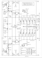
This is where I found the 275mA idle current.
Hans
Oh. I was wondering where did you get that number but I have had it all the time too.
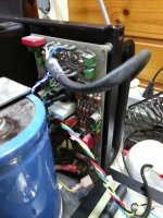
The disconnected yellow cable is the P210 to opto coupler. Black thick cable is the input cable to the main board. Not sure why it starts with four wires and ends with three(+ and -balanced and ground)
I’m almost horrified by the huge cable mess.
That must have been a very expensive production process and a complication when trying to repair.
But at the end, the ML23 is praised in many test as a super sounding amp,
Hans
That must have been a very expensive production process and a complication when trying to repair.
But at the end, the ML23 is praised in many test as a super sounding amp,
Hans
- Home
- Amplifiers
- Solid State
- Mark Levinson No23 repair help