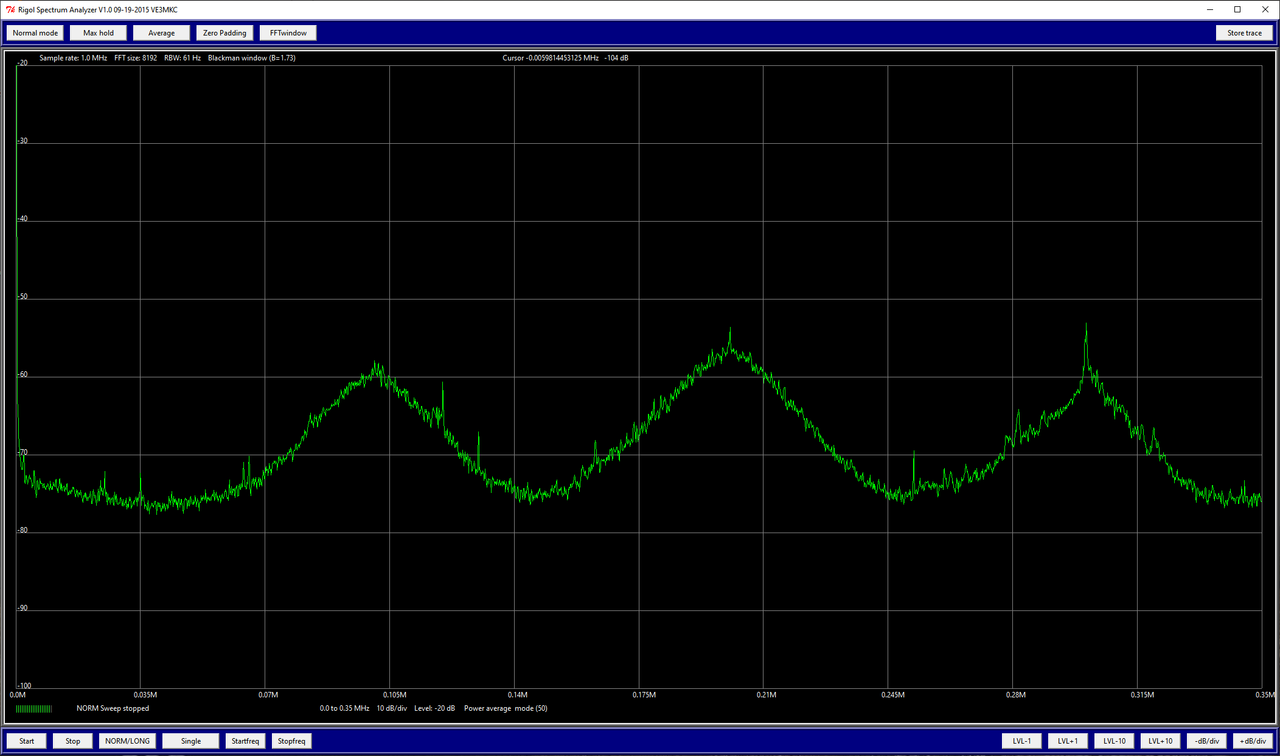
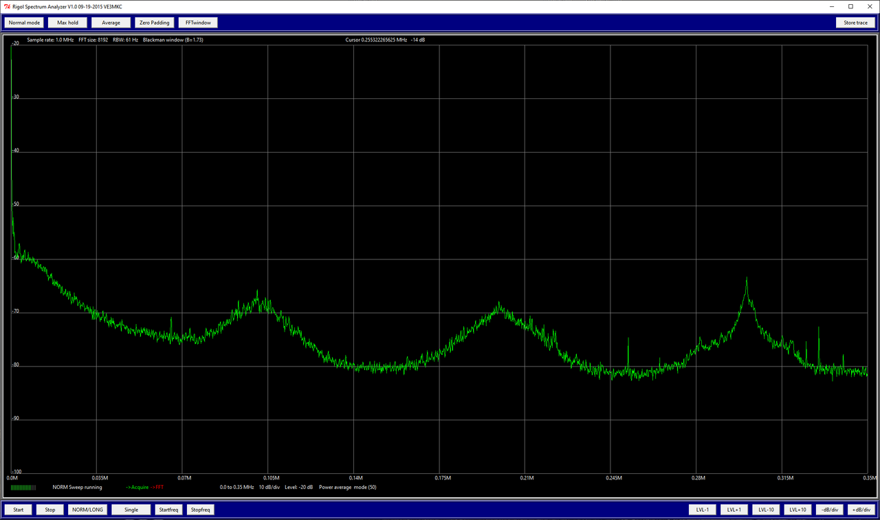
Last picture is the VReg that was especially noisy before (where I have the temp 470uF cap).
Note the range 0-70kHz, I suspect this will be the difference to silent ML, looking at the graph from a switch-off amp right now, what happens > 70kHz won't change.
So I expect the < 70kHz db is consistent with mVpp I saw before for all 4 Vregs on the scope.
Note the range 0-70kHz, I suspect this will be the difference to silent ML, looking at the graph from a switch-off amp right now, what happens > 70kHz won't change.
So I expect the < 70kHz db is consistent with mVpp I saw before for all 4 Vregs on the scope.
O.k.
So the Vreg is producing loads of noise on the bad amp.
Now comes the difficult part.
Measure R201 and R202 with reference to the gnd side on R219 / R220.
Hans
So the Vreg is producing loads of noise on the bad amp.
Now comes the difficult part.
Measure R201 and R202 with reference to the gnd side on R219 / R220.
Hans
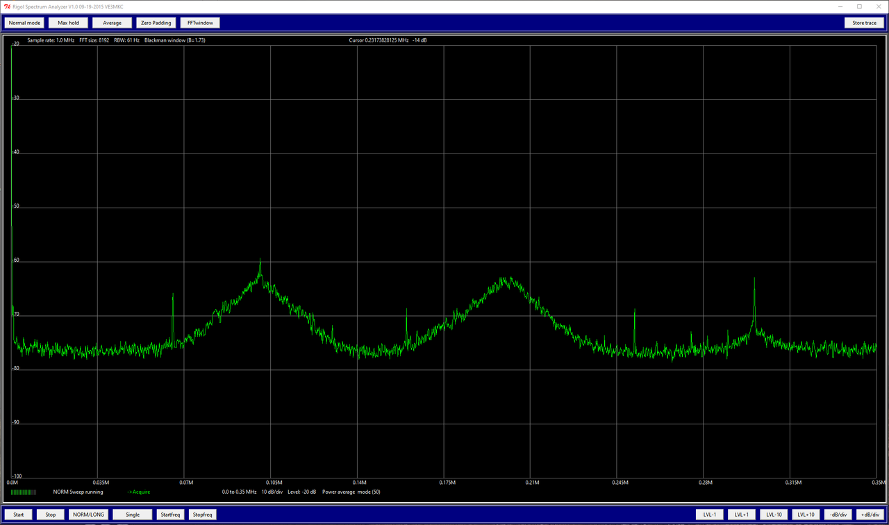
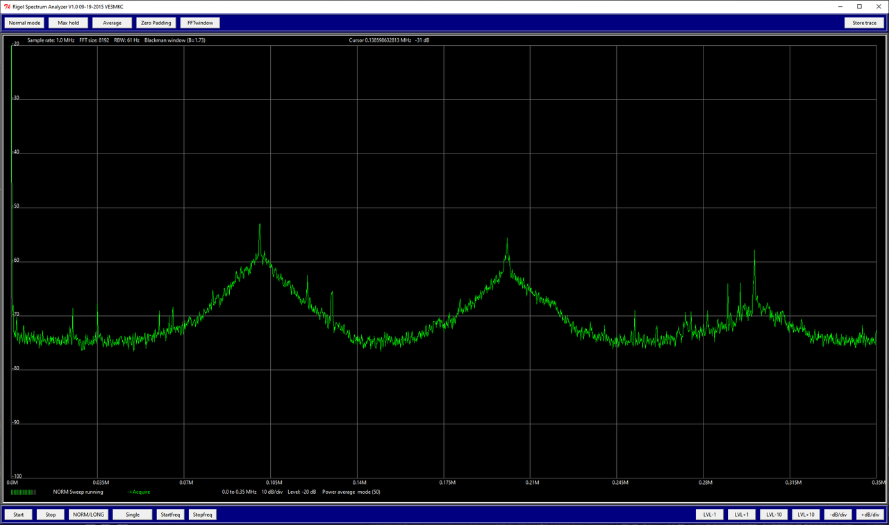
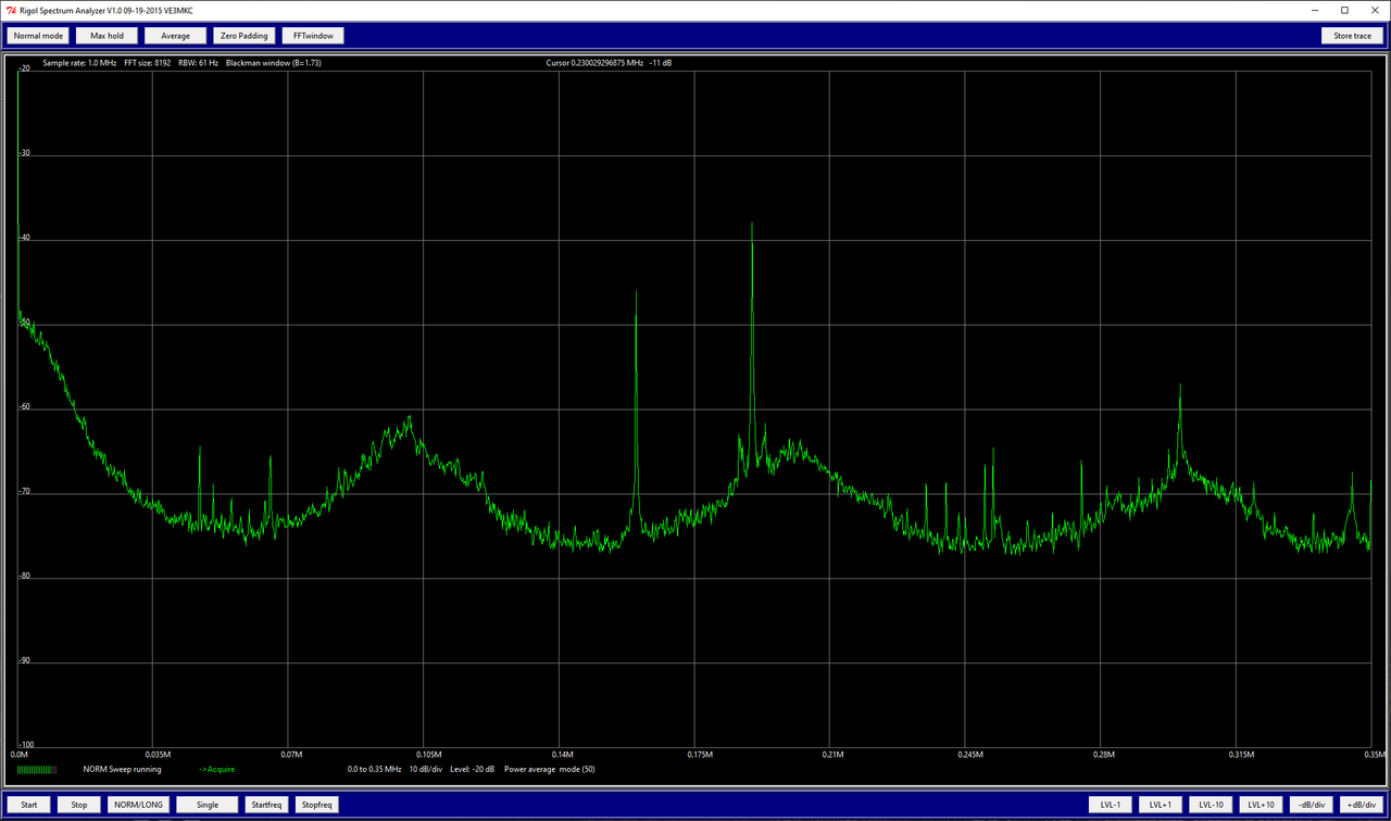
I did the noisiest VReg (right +), R201 (C201 side) with reference to gnd side of R219.
Vpp avg. 30mV there in scope.
Notice the 20db spike at 160kHz.
I made a reference measurement and the spike, in fact everything > 70kHz, has nothing to do with R201 (it is EFM).
Vpp avg. 30mV there in scope.
Notice the 20db spike at 160kHz.
An externally hosted image should be here but it was not working when we last tested it.
I made a reference measurement and the spike, in fact everything > 70kHz, has nothing to do with R201 (it is EFM).
Last edited:
That concludes the search.
You will have to remove the upper boards from the base board.
I will give you further steps when done.
Hans
You will have to remove the upper boards from the base board.
I will give you further steps when done.
Hans
Ok, there is a way to keep the upper board operational while disassembled, as you wrote earlier.
Will take me some time.
BR
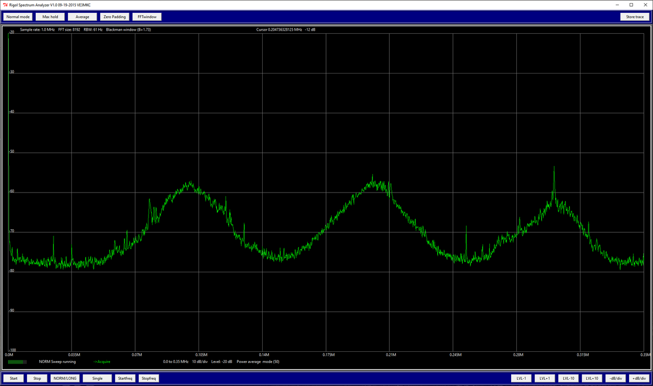
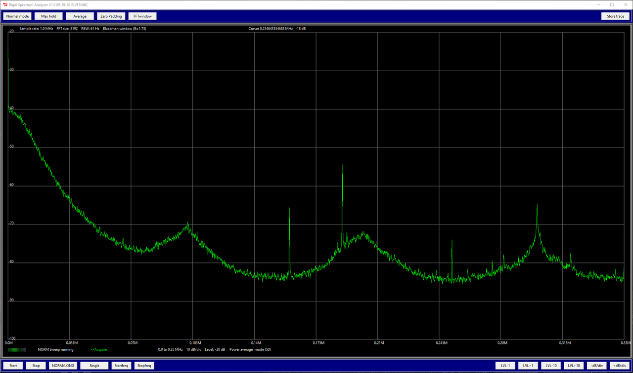
PS: Here the other Vreg of the channel for reference.
Will take me some time.
BR
PS: Here the other Vreg of the channel for reference.
When you don’t have them you can already order 4 times 22uF/63Volt to replace C201 / C202.
And there is a way to keep the base board operational without the upper board.
When I’m right the Vunreg is 90Volt, right ?
And the current flowing from P1 to P2 is 23 mA.
So what you need are two 10 watt resistors of 90V/23mA =3k9, correct me when I’m wrong with these figures.
With these 2 resistors we can fully test the regulated power supply on the base board.
Hans
Last edited:
And having thought about the two 10 watt resistors, I think it’s better in your case to connect them to the Vreg.
So they should be 65V/23mA = 2K7 @ 10Watt.
Hans
So they should be 65V/23mA = 2K7 @ 10Watt.
Hans
And having thought about the two 10 watt resistors, I think it’s better in your case to connect them to the Vreg.
So they should be 65V/23mA = 2K7 @ 10Watt.
Hans
Just so I understand: remove the upper board (AC8.5) fully and keep the lower board operational (with the heatsinks and transistors still attached).
Therefore: P6 and P7 (Pos+Neg Drive) fed by VReg P1, P4 from same board via 2K7 @ 10Watt to get that 23mA.
VUnreg disconnected, V_Prereg (via 1900uF) stays connected.
Will take me some time to set this up, will be back.
BR
Last edited:
There are two options:
1) The complete output stage with predrivers and all the transistors on the heatsink are operational.
In that case connect via the 2k7 resistors P1 to P6 and P4 to P7.
Further connect all the 4 big blue caps to the pcb.
When not having the heatsink mounted to the chassis, you will have to electrically connect the heatsink with a wire to the chassis and also to connect the two big blue caps with wires to the PCB.
Last step is to connect the thick black gnd to P18
In this setup everything works on the lower board including bias, soft start and output protection.
2) the second option is to do the above, but don’t connect the big blue caps to the PCB, leave P6 and P7 open and connect the two 2k7 to each other, to load the regulated power supply through P1 and P4 with the current that normally would flow.
Now the whole output stage is disabled, but that’s no problem as you can perfectly test the regulated supply.
Hans
These are the power supply wires of the channel, they are 190v I confused only in one channel when the Cr207 diode burst.
Hi M.L.,
any tips & tricks on how to unsolder / solder those pins connecting the boards? Did you just use an angled solder tip to reach between the boards? My solder iron is too thick to even reach in there. Perhaps it's obvious to you guys, it's not to me 🙂
Can you perhaps pls past a photo of what you used for soldering inside?
@Hans: thank you, will go with option 2 I think.
BR
Last edited:
You can only remove it with a good desoldering pump. Gently soldering iron can damage the parts.
Yes, my guess is, even with a solder pump, you'd have to warm the other side with a 2nd iron so it sucks the tin from the opposite side fully as well. We will see. I have to order a new solder tip for this.
BR
BR
I have easily turned out without heating the other side. You can add a little flux and a new solder will not be needed yet.
You can only remove it with a good desoldering pump. ..
Btw, which suction pump do you have?
BR
Do you happen to know if the SS-331 would be an upgrade to the ZD-915 (which I have)?
The Proskit likes like an ZD-8915.
EDIT: so it's probably the same
Cannot justify a (new) Weller right now.
The Proskit likes like an ZD-8915.
EDIT: so it's probably the same
Cannot justify a (new) Weller right now.
Last edited:
I don't know. And what prevents you from trying to dismantle using zd? 400 degrees for dismantling will be enough.
- Home
- Amplifiers
- Solid State
- Mark Levinson No.27 amplifier,,,NEED HELP