I took measurements on the one channel C2268 (previously burning up all the time). Across this capacitor the voltage is:
2.65volts || bias trimmer set to maximum value (100ohms lowest bias)
3.25volts || bias trimmer set to minimum value (0 ohms highest bias)
If we divide 3.25 by 6 (and its 6 because there are those 6 B/E junctions to forward bias) we get 0.54v which is not really enough.
So why would it be OK before all this happened you might think... well I'm going to suggest that the replacement transistors are slightly different in there manufacturing process and that B/E is going to need to be a bit higher.
You MUST use the bulb for this initially but I would suggest reducing the value of the 270 ohm in series with the preset. Easiest way is just to add a parallel resistor. Try a 1k and be sure to start with the preset on max value (for lowest voltage and lowest bias).
Try it on one channel.

Q7266 is a 2SA1360 https://www.mouser.com/datasheet/2/408/2SA1360_datasheet_en_20100310-706803.pdfMaybe.
If Q7266 is functional, there should be about 0.6V base-emitter voltage.
If there isn't, the base junction might be shorted, and the collector open. No current to bias spreader.
Or, R3294 or its conducting traces might be open or too high resistance. Base-emitter voltage is then low because there's no current through R3294. No current to bias spreader.
Since you confirm 150 ohm resistance, open traces are a possibility. What is b-e voltage? If it's too low, why?
This issue has to be sorted IMHO.
I've checked continuity both for the resistor R3294 and this transistor and from the board / connections tandpoint everything checks out fine.
B-E voltage is 600mv but that's what i would expect
Also i have replaced this transistor previously while i was trouble shooting bias so it is new and still checks out fine.
When the Q7266 issue is solved and the above is correct, the problem has to be found in the output transistor circuit or perhaps beyond.
What are the emitter readings on 7222, 7274, 7276 and 7278 with respect to ground and the bias pot all the way up and all the way down?
Again two reading for each transistor.
Hugo
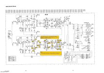
I have already measured all voltages relative to ground on all those transistors with bias at a minimum. Re attaching schematic on this post.
The negative side is wayyy low i can see that but that has to do with the bias trimmer. When i increase bias those voltages on the negative side increase but are still on the low side.
Too scared to measure all of them at full bias on the trim pot because last time it fried the outputs while measuring. And i did not touch / short anything.
I don't want to blow the outputs again. This is my 4th set of output transistors!! And since it is a 4 channel that's 8 transistors (4 per channel)!
Across R3302 i measuretook a closer, more careful look at your post. If you observe 1.6V directly across the resistor leads and you confirm 150 ohm, that does indeed suggest a bit more than 10mA flowing. Question, where is it flowing? If through collector and into bias spreader, what voltage do you observe across R3302 in the spreader?
Just saw Hugo's post. Points well taken.
463mv When bias is at a minimum setting (~100 ohm)
602mv When bias is at a maximum setting (~0 ohm)
If we divide 3.25 by 6 (and its 6 because there are those 6 B/E junctions to forward bias) we get 0.54v which is not really enough.
So why would it be OK before all this happened you might think... well I'm going to suggest that the replacement transistors are slightly different in there manufacturing process and that B/E is going to need to be a bit higher.
You MUST use the bulb for this initially but I would suggest reducing the value of the 270 ohm in series with the preset. Easiest way is just to add a parallel resistor. Try a 1k and be sure to start with the preset on max value (for lowest voltage and lowest bias).
Try it on one channel.
I fully understand what you are describing but the schematic ideally states +1.6v on one side and -1.6v on the other. So i would expect 3.2v as per the schematic.
I'vw done that previously with the bias trimmer almost all the way up (~15ohms of the 100ohm range) and i got really close. I still could not measure bias on the output resistors and it blew the outputs again.
The only way i have managed to test extensively right now is to keep bias at a minimum. If i need to measure on maximum bias i turn it on for a few seconds take the measurements and then shut it off. So the measurements i'm taking are when the transistors are cold so the measurements are not 100% accurate. I should let it warm up first.
I would like to try what you are suggesting with the parallel resistor and it makes a lot of sense but i can't keep blowing output transistors this has become tedious now.
What happens if i leave the amplifier like this? I would work like a class B right? Could it cause any more damage if i leave bias as low as it is now?
Also i still havent figured out why it blew in the first place. All it came with was broken solder joints. The only common denominator here was that both bias trimmers where set to ~15ohms out the 100 ohm range. So i assumed that the bias was too high and it blew.
Attachments
Last edited:
So why would it be OK before all this happened you might think... well I'm going to suggest that the replacement transistors are slightly different in there manufacturing process and that B/E is going to need to be a bit higher.
The more i think about it the more it makes sense to me. On the left / good channel that blew recently the only thing i replaced is the output transistors and the emitter & base resistors.
I asked one of my old proffessors at the university and he told me the same exact thing. That the new transistors have different characteristics and could be that the trimmer is now out of range and that i need to change the value of 270 ohm and see what happens. But still wouldn't i be able to SOME bia there? even if it is 1mv. I see nothing! The only time i see any bias even on minimum volume is when i connect a load / speaker. Without a load it is always zero
Obviously i'm terrified to do that. WOuld the dim bulb save the outputs if something goes wrong here? I REALLY don't want to blow them again
Last edited:
And a question from me too, from where you bought the replacement transistors??
I bought them from local retailers here in greece. (Soundservice.gr)And a question from me too, from where you bought the replacement transistors??
I would prefer authorized supplier.
It is better to use good original replacement parts than unknown fake parts.
It is better to use good original replacement parts than unknown fake parts.
Do you believe those are fake? I've been buying fake parts all along?I would prefer authorized supplier.
It is better to use good original replacement parts than unknown fake parts.
Should i use mouser then do you have any other supplier to recommend?
Fake parts are common problem in Greece and all over the world!
You can't trusted any other than the authorized supplier like Mouser or Digikey.
I would strongly suggest Mouser.
You haven't pay for import taxes.
Use 2SC5200,A1943.
It's better than chasing ghosts.
You can't trusted any other than the authorized supplier like Mouser or Digikey.
I would strongly suggest Mouser.
You haven't pay for import taxes.
Use 2SC5200,A1943.
It's better than chasing ghosts.
Wow i did not know that! You know what? Just for the sake of argument i will order 4 pairs from mouser.Fake parts are common problem in Greece and all over the world!
You can't trusted any other than the authorized supplier like Mouser or Digikey.
I would strongly suggest Mouser.
You haven't pay for import taxes.
Use 2SC5200,A1943.
Why should i use 2sc5200 and a1943? Are those better?
Because the type you have isn't available anymore.
Another suggestion from me
You don't need two pairs for testing.
Use one pair for each Chanel.
As soon as you will have a fully functional amplifier you can add the second pair.
Just keep the volume low and do not test hardly.
Another suggestion from me
You don't need two pairs for testing.
Use one pair for each Chanel.
As soon as you will have a fully functional amplifier you can add the second pair.
Just keep the volume low and do not test hardly.
Last edited:
Now that you say that i was not able to find the original transistors and only sounddervice.gr had them in stock. Maybe i'm using fakes all this time.Because the type you have isn't available anymore
I will buy 10 of each from mouser gain match them and test again:
2SA1943: https://eu.mouser.com/ProductDetail/Toshiba/2SA1943-OS1F?qs=B6kkDfuK7/Cm3tZSt%2BISCw==
2SA5200:
https://eu.mouser.com/ProductDetail/Toshiba/2SC5200-OQ?qs=EEns8I54Y6BCHV7Kwts0vw==
Please verify i'm looking at the correct transistors
You can't match having 10 pairs only
You need a lot of them to match but this is no so critical.
I have so many diy amplifiers with multiple out pairs not matched
You need a lot of them to match but this is no so critical.
I have so many diy amplifiers with multiple out pairs not matched
Service manuals can be very inaccurate at times. The voltages they show may be little more than expected ball park figures. For example they clearly show 0V on the emitter of both output transistors and so by definition there is zero bias current flowing. 0 volts across 0.36 ohm is zero amps.I fully understand what you are describing but the schematic ideally states +1.6v on one side and -1.6v on the other. So i would expect 3.2v as per the schematic.
An experienced tech can pencil in all the expected voltages on all the nodes in any circuit like this in seconds without having to measure anything... and while they will be 'correct' the real world voltage will vary slightly.
Bias out of range after replacing original parts is something we see quite often.
It should do. That is the whole point of it. Provided the outputs are fitted to the heatsink correctly the bulb can't pass more current than the outputs can handle, more correctly the bulb limits the total power the amp can draw which can never be more than the bulb rating.WOuld the dim bulb save the outputs if something goes wrong here? I REALLY don't want to blow them again
I will try to get them as close as possible then. I can't afford to buy more than ten of each. Those will cost about 50€ so yeah.. thank you for bringing this to my attention.You can't match having 10 pairs only
You need a lot of them to match but this is no so critical.
I have so many diy amplifiers with multiple out pairs not matched
Service manuals can be very inaccurate at times. The voltages they show may be little more than expected ball park figures. For example they clearly show 0V on the emitter of both output transistors and so by definition there is zero bias current flowing. 0 volts across 0.36 ohm is zero amps.
An experienced tech can pencil in all the expected voltages on all the nodes in any circuit like this in seconds without having to measure anything... and while they will be 'correct' the real world voltage will vary slightly.
Bias out of range after replacing original parts is something we see quite often.
It should do. That is the whole point of it. Provided the outputs are fitted to the heatsink correctly the bulb can't pass more current than the outputs can handle, more correctly the bulb limits the total power the amp can draw which can never be more than the bulb rating.
I don't have that kind of experience obviously. This is a hobby. I was lucky enough to do repairs on small amplifiers with tdm or STK chips so this is my first class ab. I learned a lot so far from this adventure.
Since i'm planning to buy original parts from mouser this time (i suspect those i have are fake)
i will test with the dim bulb (65w bulb) and a 200ohm resisotr instead of a 270ohm. And See what happens then. If they burn up again i will replace them with those:
I will buy 10 of each from mouser gain match them and test again:
2SA1943: https://eu.mouser.com/ProductDetail/Toshiba/2SA1943-OS1F?qs=B6kkDfuK7/Cm3tZSt%2BISCw==
2SA5200:
https://eu.mouser.com/ProductDetail/Toshiba/2SC5200-OQ?qs=EEns8I54Y6BCHV7Kwts0vw==
Keep in mind that you need original parts for other positions too,like Vbe multiplayer that already replaced.
They shouldn't do. The bulb WILL stop that happening.i will test with the dim bulb (65w bulb) and a 200ohm resisotr instead of a 270ohm. And See what happens then. If they burn up again i will replace them with those:
Oh my god... the left channel which was constantly frying the the outputs has been completely rebuilt.. all transistors there have been replaced.. i need to reorder all of those and replace them again.. what a nightmare... i should have known better this is my fault..Keep in mind that you need original parts for other positions too,like Vbe multiplayer that already replaced.
And to top it all off i found this thread:
https://www.diyaudio.com/community/threads/chinese-fake-transistor-experiment.349875/
This guy explains the exact same thing!! So yeah.. i really start to believe that the parts i used are trash...
Thanks again!
Before you order at Mouser, it would be worthwhile to check the other transistors you replaced.
They could be fake as well. Virtually no transistor in this amp is available anymore at the regular sources.
Did you buy them at soundservice as well?
Hugo
They could be fake as well. Virtually no transistor in this amp is available anymore at the regular sources.
Did you buy them at soundservice as well?
Hugo
No, it's the faker's fault. And you pay for the learning curve...i should have known better this is my fault..
Hugo
- Home
- Amplifiers
- Solid State
- Marantz PM-68 Keeps Frying Output Transistors on Right Channel