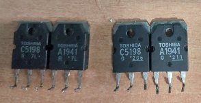
No i could not find them there i found them from another greek retailer markidis.grBefore you order at Mouser, it would be worthwhile to check the other transistors you replaced.
They could be fake as well. Virtually no transistor in this amp is available anymore at the regular sources.
Did you buy them at soundservice as well?
Same situation though. He was the only one that had had those transistorsno one else had them.
Appearance-wise they looked the same BUT the legs of those transistors looked very cheap / soft compared to the originals.
At first i thought that since its been 20 years they changed the materials.
I didn't even think for a second that there are fake transistors out there. I thought the codes for the transistors would be different or a different brand.
I never thought that a transistor indicating the toshiba logo would be fake. I thought that it would mention some other brand that is a supposed replacement for the originals if it was fake.
This is a quick working simulation to show you how base/emitter volts varies between devices. Each transistor has been biased to give around 30 milliamps in the 0.18 ohm resistor. Look at the different base voltage that needs to be applied for each.
Real world parts vary like this as well. The MJE15032C in this example and if all your replacements were like this would need around 0.64*6= 3.84v to be developed across the vbe multiplier in order to get any current flowing.

Real world parts vary like this as well. The MJE15032C in this example and if all your replacements were like this would need around 0.64*6= 3.84v to be developed across the vbe multiplier in order to get any current flowing.
Be careful, I made this mistake, the link shown to 2sc5200-O and 2sa1943-O shown a pic of the wrong package. These devices are in toshiba version of a to-264
The toshiba TO-3p version part numbers are 2SA1943N(S1,E,S)
2SC5200N(S1,E,S)
The toshiba TO-3p version part numbers are 2SA1943N(S1,E,S)
2SC5200N(S1,E,S)
Last edited:
Thank you for being so thorough an going through the trouble of showing me this. I fully understand this now.
The problem now is that:
let's say i prove your point with the lower value resistor and manage to get it to bias. If the parts i used are fake then it will blow them again.
So i have 2 options:
Leave it unbiased for now and let it work as a class b.
Get some rest leave it for a couple of weeks alone while new genuine parts arrive from mouser and test / measure everything again.
Are you keep the original small signal transistors that you have replaced?
If so, measure eatch one for go no go .
You need to place it's one in it's original position again.
If you will find shorted small signal transistors post the type here and Mooly or someone else will suggest you a suitable one replacement from today available series.
Yes, rsavas ,is right 👍
If so, measure eatch one for go no go .
You need to place it's one in it's original position again.
If you will find shorted small signal transistors post the type here and Mooly or someone else will suggest you a suitable one replacement from today available series.
Yes, rsavas ,is right 👍
Good catch i did not see that. Once im ready to order them i will check twiceBe careful the link shown to 2sc5200-O and 2sa1943-O shown a pic of the wrong package. These devices are in toshiba version of a to-264
The toshiba TO-3p version part numbers are 2sa1943n and 2sc5200n
You'll need to find substitutes for:
2SA1360 / 2SC3423
2SC3419
BF422 / BF423 -> Available at Mouser
2SC4793
2SA1837
Perhaps the 1N4148 diodes?
Perhaps the zeners 3V6 / 0.4Watt
Don't know if you replaced Q7261 (2SC2240)
Hugo
2SA1360 / 2SC3423
2SC3419
BF422 / BF423 -> Available at Mouser
2SC4793
2SA1837
Perhaps the 1N4148 diodes?
Perhaps the zeners 3V6 / 0.4Watt
Don't know if you replaced Q7261 (2SC2240)
Hugo
Your welcome 🙂 I'll just add this to show you how the current can alter with a seemingly miniscule change in applied base voltage. So we can't use vbe as a means of adjusting anything and yet it remains one of the most useful measurements in fault finding.Thank you for being so thorough an going through the trouble of showing me this. I fully understand this now.
If we increase the base voltage by just 0.01 volts we see an increase of 35% in the current in the 0.18 ohm resistor.
That is impossible to answer because it depends what the actual device is.let's say i prove your point with the lower value resistor and manage to get it to bias. If the parts i used are fake then it will blow them again.
If the devices are fake they can still fail under load. They may have an inadequate voltage rating and/or a low current rating. Its an unknown.Leave it unbiased for now and let it work as a class b.
Genuine parts are always good. 99% of all failures only involve the outputs and drivers, in other words everything to the right of the bias generator.Get some rest leave it for a couple of weeks alone while new genuine parts arrive from mouser and test / measure everything again.
No i did not keep them but after repeatedly frying the outputs on that channel they tested wrong so there was no point. In that channel everything has been replacedAre you keep the original small signal transistors that you have replaced?
If so, measure eatch one for go no go .
You need to place it's one in it's original position again.
If you will find shorted small signal transistors post the type here and Mooly or someone else will suggest you a suitable one replacement from today available series.
Yes, rsavas ,is right 👍
Transistors, resistors, diodes including zeners and electrolytic capacitors.
I will deal with this tomorrow. I will order everything again from mouser.You'll need to find substitutes for:
2SA1360 / 2SC3423
2SC3419
BF422 / BF423 -> Available at Mouser
2SC4793
2SA1837
Perhaps the 1N4148 diodes?
Perhaps the zeners 3V6 / 0.4Watt
Don't know if you replaced Q7261 (2SC2240)
Hugo
U have already replaced the zeners and the other diodes. I hope those are not fake also
You haved placed all the original in the bin?
I this case you need to use replecements.
Let's wait what will suggest here.
I this case you need to use replecements.
Let's wait what will suggest here.
Mouser are out of stock for the 2sa1943n until they say the end of month, Digikey may have stock, need to check.
But imo perform the test as Mooly suggested and lower the 270 ohm resistor (r3302) to the next standard E12 value being 240. You can put a resistor in parallel with the 270 as a test. Using a 2k||270 gets you close to 240. This will allow a higher bias spread voltage since the bias sense transistor (q7268) will not be turned on as much. You could also go lower to 220 and replace the 100 ohm pot with a 200 or 500 ohm pot to have a larger adjustment range.
But imo perform the test as Mooly suggested and lower the 270 ohm resistor (r3302) to the next standard E12 value being 240. You can put a resistor in parallel with the 270 as a test. Using a 2k||270 gets you close to 240. This will allow a higher bias spread voltage since the bias sense transistor (q7268) will not be turned on as much. You could also go lower to 220 and replace the 100 ohm pot with a 200 or 500 ohm pot to have a larger adjustment range.
Last edited:
I will perform that test on the dim bulb as mooly suggested. My problem now is that once they are biased the fakes tend to fail. So if i do get it to bias i will set it low. The manufacturer states 19mv +-3mv. I will bias then at 10mv and see how long they last hahaha. I guessing i will see the magic smoke for the 6th time now...
Could you crack one of these probably fake outputs so we can see what's inside?
Hugo
Hugo
Live and learn 🙂
Imo it’s better to use the toshiba 2sa1943n/2sc5200n from mouser or Digikey since they are 150w devices and have a long reputation on quality. I’ve used >100 of them and never heard of a issue yet. Same goes with onsemi devices, njw0281/0302 which are more $.
Recently I bought some SPTech devices from LCSC to try out and compare, the prices are significantly less than the onsemi devices but the real testing needs to be performed to see if they are up to the task.
Last edited:
I will try and post pics.Could you crack one of these probably fake outputs so we can see what's inside?
Hugo
Just a side note since i have replaced them many times.Mouser are out of stock for the 2sa1943n until they say the end of month, Digikey may have stock, need to check.
But imo perform the test as Mooly suggested and lower the 270 ohm resistor (r3302) to the next standard E12 value being 240. You can put a resistor in parallel with the 270 as a test. Using a 2k||270 gets you close to 240. This will allow a higher bias spread voltage since the bias sense transistor (q7268) will not be turned on as much. You could also go lower to 220 and replace the 100 ohm pot with a 200 or 500 ohm pot to have a larger adjustment range.
In previous repairs even though i could not get them to bias and the trimmer was left at the default 20ohm. They where blowing after 10-15 minutes. The only way i can get thrm ti last is if the bias is at minimum. So if i do the test mooly suggested i will definitely fry them 100%.
The only solution is to buy the updated original ones from mouser once they are in stock and report back (after a month? 2 months? Until they become available in stock?)
I will crack them open and post pictures of what's inside. I have a couple of 2sa1941 that still measure fine. And post pictures
Farnell has them in stock but you need a VAT number or someone who has one and is willing to buy them for you.after a month? 2 months?
Hugo
If they are fake parts, it could be voltage break down that causes the smoke regardless of what bias current was set too. A different failure mode.
Start fresh with guaranteed semis, with zero bias power up on DBT, let it soak, check voltages as you did previously, then test/adjust bias. Remember that when on the DBT the supply voltages are lower, depending on the design this can lower vas current affecting the bias spreader voltage range, in some cases the bias generator voltage range is not sufficient to achieve the spec ops bias current. Every different set of parts in the 3ef ops has some Vbe variation that must fall in the bias generator adjustment range. The bias spreader voltage range also depends on the voltage amp (vas) current and the parts in the Vbe multiplier ckt.
If you provide the info on exactly what parts you are using, and we have models it’s pretty easy to do a sim on this amp and characterize it. The bulk of the work is entering the schematic in Ltspice, something every person working on amps could make very useful in understanding how these amps work, that and reading Bob Cordell’s power amp design book which spells it all out in 600 pages 🙂
Last edited:
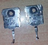
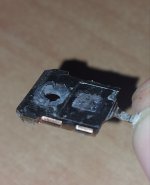
In this post i have attached photos of the 2sc5198 from the previous batch tha burned up. I don't know how a fake would look like inside but here it is. Awaiting for your comments..
Attachments
- Home
- Amplifiers
- Solid State
- Marantz PM-68 Keeps Frying Output Transistors on Right Channel


