Hi. Could you check pictures there is red circles my friend signed? He wants to know Where are they connecting
Yes there is thin circles that my friend circled on the left and right. Difficult to seem ,needs enlarging picture

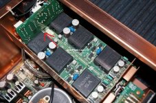
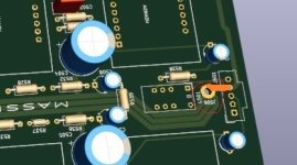
Those marked points (J504, J505) in the 3D photo are just the vias connecting the upper and lower layers.
In the photo below you can see that there is a wire soldered to J504, this probably goes somewhere on the chassis.
In the photo below you can see that there is a wire soldered to J504, this probably goes somewhere on the chassis.
Attachments
Last edited:
Yes there is thin circles that my friend circled on the left and right. Difficult to seem ,needs enlarging picture
This is where the path is missing, I marked with an orange line.
Attachments
Last edited:
There is no J506 in that location. It is actually J505. J505 connects J501 and to J503. J503 is then grounded through the PCB mounting hole screw. J505 also has a wire soldered in it that goes down to the chassis bottom plate and connects to ground there.
It is like this on the PCB:

It is like this on the PCB:
Markw4
My post above was to Veysel, I misquoted but already corrected.
Your information is valuable because the pictures don't show all the ground wires.
My post above was to Veysel, I misquoted but already corrected.
Your information is valuable because the pictures don't show all the ground wires.
Thanks a million for the help and the pictures Mark ! This amplifier is a pure art.We are clonning it.We hope we can work it well.Maybe i can make it only one pair of output because of i do not need such high wattage but want to experience this amplifiers quality.
Maybe better to make it as Marantz intended, sell it to a rich audiophile, then use the earnings to help pay for yours 🙂
Otherwise, it wasn't really designed to run with one end of the speaker tied to ground. You might have to tweak the circuit a little for that to work optimally.
Otherwise, it wasn't really designed to run with one end of the speaker tied to ground. You might have to tweak the circuit a little for that to work optimally.
Hi Mark! We will order choke input transformer from transformer producer. But do not know how to describe it.Is it built like an emi filter or toroidal transformer. Any datasheet or example? Regards Umit
I have yellow cores.But it seems they are made with toroidal transformer cores because 180mH value is high.
Last edited:
Ok I see. We also need to know at which frequency 0.18mH coils inductance measured.
Not critical as long as it exceeds 180mH. If the current is known it's easy to calculate the critical inductance for choke input.
I don't really see the point of obsessing about that choke. It's contribution to the overall sound is quite minor imho.
- Home
- Amplifiers
- Power Supplies
- Marantz MA9S2 choke input power supply