poynton said:HI.
To find the source of the noise and so reduce / eliminate it, you need to measure earlier preferably just after the dac.
Andy
Hi Andy,
I've done that already, the DAC's outputs show a nice square wave 😀.
After that, a 1kHz sinewave on a test cd gets clearer and clearer after the first stages of passive filtering. The first opamp is supposed to subtract both signals, but at it's inputs, the two waves seem to be in phase (???).
There's still too much HF at this point to discover any noise (on my simple 20MHz scope that is...🙁).
Ray.
I am changing every thing in the HF amp tomorrow with nice parts and then the RF later in week. 😀
Has anyone thought about changing the xtal on the servo or is this a waste of time?
Has anyone thought about changing the xtal on the servo or is this a waste of time?
Originally posted by Bas Horneman
Haven't started yet...maybe tonight
NO hurries mate.
Thanks...but that would be a waste of a great sounding CD player..since I'll would probably end up using it as a transport for my RAKK DAC.
Yeah, that 63 it's a bit overdone....
The tubestage sounds great, but it also has a few minor disadvantages. The amplification is low (1x), and since the signal is divided by the passive filter, the output is not all that.
I'm going to see if I can solve that by using a long-tailed diff. input stage with a low-mu tube. Then I can sum the input signals also. The tubes are not in series then, so B+ can be lower. If I use one with low Ri then the output impedance should be low enough so I won't need a kathode follower buffer. I already tried with a ECC82 (I simply modified the exsisting circuit) and got a HUGE output. It needs some tweaking 😀.
Regards,
Ray.
6h5c said:
I'm going to see if I can solve that by using a long-tailed diff. input stage with a low-mu tube. Then I can sum the input signals also. The tubes are not in series then, so B+ can be lower. If I use one with low Ri then the output impedance should be low enough so I won't need a kathode follower buffer. I already tried with a ECC82 (I simply modified the exsisting circuit) and got a HUGE output. It needs some tweaking
Regards,
Ray.
Hi Ray.
So now you have something similar to mine but without the cascode???
Andy
PS
I read, in one of the many articles on modding the '63, that it is VERY important to have matched components after the dac to give a balance. Of course, any imbalance would give rise to residual noise.
rowemeister said:I am changing every thing in the HF amp tomorrow with nice parts and then the RF later in week. 😀
Has anyone thought about changing the xtal on the servo or is this a waste of time?
Hi Brent!
Like your pictures! You did a nice job on the PSU.
In my 67 the servo/decoder is one chip fed from the DAC clock, so that's that for me 😀.
If the PSU around the 63's servo is improved it may have a positive effect since less noise will be present in the player.
Ray.
rowemeister said:
Has anyone thought about changing the xtal on the servo or is this a waste of time?
Since the servo osc. is 8.46Mhz, divide the dac clock by 2 and use 1 clock ?????
Andy
Originally posted by poynton
Hi Ray.
So now you have something similar to mine but without the cascode???
Yep, that's right. I tried it with one channel only. I re-arranged the wiring of Thorstens circuit and upped the current through the FET to 8mA. I used 10k anode resistors.
I read, in one of the many articles on modding the '63, that it is VERY important to have matched components after the dac to give a balance. Of course, any imbalance would give rise to residual noise.
I know that one. My tube-proto is not that balanced, but my 67 and 63 use 0,1% resistors and 1% matched caps. But there's still noise. Have you found it as well in your player?
Regards,
Ray.
6h5c said:
Yep, that's right. I tried it with one channel only. I re-arranged the wiring of Thorstens circuit and upped the current through the FET to 8mA. I used 10k anode resistors.
I know that one. My tube-proto is not that balanced, but my 67 and 63 use 0,1% resistors and 1% matched caps. But there's still noise. Have you found it as well in your player?
Regards,
Ray.
Hi Ray,
Sorry, I cannot be of help in that respect right now!!
I have just started to rip the audio stages off my board in preparation for the tube stage.
I am also rewiring the redundant +-12v opamp supply to give +12v only as a preregulator for +5v.
Andy
Ah, good luck with that. Didn't do that yet. There's enough possibilities to mount Thorsten's filter on the PCB, using the original holes and traces. It will be nicely close to the DAC.
I was hoping to use the 12V for heater supply 😀. Not enough current i'm afraid. Maybe the windings can be paralleled?
Anybody heard from Michael yet, regarding our custom toroid?
Hey Michael, how are you 😉?
Regards,
Ray.
I was hoping to use the 12V for heater supply 😀. Not enough current i'm afraid. Maybe the windings can be paralleled?
Anybody heard from Michael yet, regarding our custom toroid?
Hey Michael, how are you 😉?
Regards,
Ray.
6h5c said:..............I was hoping to use the 12V for heater supply 😀. Not enough current i'm afraid. Maybe the windings can be paralleled?...........
Hi,
Windings are centre-tapped except, maybe, the KI. It may be possible by removing the TX and checking out the wiring but I would not think so.
Andy
rowemeister said:Divide clock by 2...mmmmm
What is the prefered ic for doing this job?
d-type flip-flop 74hc74
rowemeister said:😉
Do you have a schematic at hand or do I have to find one myself 🙂 hehe
cheers
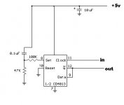
HI.
Something like this........................
Power on reset ( SET actually ) is possibly not required.
Use 74HC74 or 74AHC74 not CD4013 - available from Maplins.
Andy
Attachments
22mV nise seems quite high, thats about 1% of full output.
Can this player be reengineered to get rid of the noise?
Can this player be reengineered to get rid of the noise?
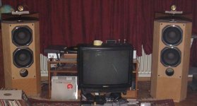
Thanks Franz. I think the noise is there, but you'll have to set your volume to max. to hear it.
I am very sorry, I just tried it: full volume, >100dB/W speakers (see foto) attached: dead silence.
My hints:
First: The most critical voltage seems to be AVDD (pin 21 and 22 from the SM5872). It is recommended, to derive it from the 12V "audio" voltage.
Second: Try analyzing the ground layout...
Franz
Attachments
rowemeister said:..........I am changing every thing in the HF amp tomorrow with nice parts and then the RF later in week...............
HI.
Probably too late but .......
Before ripping YOUR cd-p apart, I had some thoughts last night re. the servo section / HF.
The servo is, of course, a linear, non-digital section (analog).
Looking at the PSU side, the +-10 feed does not require any mods, although splitting of the digital +5v would be beneficial. This is because it is a servo and therefore 'self-adjusting'.
EXCEPT, VRef, the reference voltage for the focus, tracking and radial servos is derived from the digital +5v. It is a simple 2.5v from a potential divider, R124 /R125, decoupled by a couple of caps. Any noise on VRef will be seen by the servo and WILL affect performance adversely!!
Can you measure the noise on the +%v at R122 / C122 / R124 junction.?
It may be worth feeding this point fron the 'cleaner' analog +5v and also deriving the VRef +2.5v from a more stable source, TL431.?
Andy
Franz G said:........... Try analyzing the ground layout............
Franz
Hi Franz,
I have heard this before!
However, I, like many others no doubt, recognise that the pcb layout etc is done by a router with little regard for the sonic benefits of good grounding etc.
However, we do not possess the knowledge or tools to analise and then reconfigure the pcb.
Have you modified your Ground???
If so, please pass on the information. 🙂
Andy
I changed C120 and C122 to 16V 3300uF Pana FC.
I changed these to give more headroom. I am also going to seperate the two 5V inputs to the servo has one is for analogue and the other digital.
The voltage between the two points is 4.983V in stop mode and 4.931V when playing. Tracking etc does not affect the voltage
I changed these to give more headroom. I am also going to seperate the two 5V inputs to the servo has one is for analogue and the other digital.
The voltage between the two points is 4.983V in stop mode and 4.931V when playing. Tracking etc does not affect the voltage
- Home
- Source & Line
- Digital Source
- Marantz CD63 & CD67 mods list