Hey Ray,
Nice, I think this is the logical solution. I'm gonna start doing it like this I reckon. I have some nice insulated RCAs I can use.
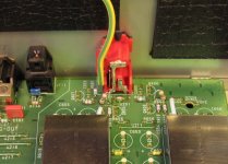
Is that a varistor I can see? And a choke? 😉 😉
Nice, I think this is the logical solution. I'm gonna start doing it like this I reckon. I have some nice insulated RCAs I can use.
Is that a varistor I can see? And a choke? 😉 😉
I have a 0.33uF cap at my power lead, which will sting the unsuspecting unplugger 
edit: please use a bleed resistor of the approprate ratings for any significant power capacitor
edit2: now I don't look too irresponsible do I?
edit3: 0.33uF at 240vac *really* hurts 😱
edit: please use a bleed resistor of the approprate ratings for any significant power capacitor
edit2: now I don't look too irresponsible do I?
edit3: 0.33uF at 240vac *really* hurts 😱
I wired my cap after the switch so when its turned off it is discharged via the TX.
My RCA cons are wired to pcb with silver wire so yep I take the back panel off still attached to the pcb.
My RCA cons are wired to pcb with silver wire so yep I take the back panel off still attached to the pcb.
Great, thanks.
I might move my mains caps when I go into her for work, it's just it's all a bit glue gunned down
I might move my mains caps when I go into her for work, it's just it's all a bit glue gunned down
SimontY said:Hey Ray,
Is that a varistor I can see? And a choke? 😉 😉
Yep, the choke nicely fits in the board. That is no coincidence, the choke is optional on the board. Farnell 322-7509 works perfectly (just in case anyone wonders, I have no stock in Farnell 😀).
edit3: 0.33uF at 240vac *really* hurts 😱
I guess you were the first unsuspecting unplugger! LOL!
Ray.
6h5c said:
Yep, the choke nicely fits in the board. That is no coincidence, the choke is optional on the board. Farnell 322-7509 works perfectly (just in case anyone wonders, I have no stock in Farnell 😀).
I guess you were the first unsuspecting unplugger! LOL!
Ray.
I stole my chokes from a computer psu. More hot melt salty porridge on my board.
I stung myself a couple of times on that cap - it's enough to leave your arm feeling funny for some minutes.. Not recommended for those using pacemakers I guess. 🙄
Maggie Thatcher reportedly used electric shock therapy and found it beneficial. Some may say the charge was too low and it did nothing for her hair! LOL
There have been posts and articles all over the place about the use of input chokes and caps. Some say good, others bad! I think the problem is that to be really effective, common mode chokes and caps to ground etc rely on a VERY good ground connection. I have an excellent article on the suject by Les Sage from the now defunct '"Audio Conversions" magazine, issue 16, from late 1992. If anyone wants, I can email a copy.
Andy
Poynton i'll have a copy please 😉
6h5c where does the earth wire go from the mains input. Just curious 🙂
6h5c where does the earth wire go from the mains input. Just curious 🙂
Hi Andy, Pls. send me a copy too, thanks.
rowemeister,
I connected the earth wire to the ground-starpoint at the RCA output socket. Seems the only sensible place. The pic is of a CD63 by the way.
I grounded my DIY tubeamp because of the high voltages, and I didn't want any ground-current going through my interconnects. So I decided to ground/earth the player too, and it works very good. I made a power block where all the equipment is plugged in, with a nice thick earth rail inside 😀
Regards,
Ray.
Attachments
I never put an earth on mine because of earth current (my KI amp has no earth neither). But with you earthing the amp I can see why you have done this. 😎
I put one on my chassis to get rid of the tingle
It certainly sounds no worse this way. It goes to an earth block that joins with the other kit via the power strip, and to house earth and equally to an earth rod I hammered into the front area outside the house... never mind that it's a rented property... 😎
The earth rod was an upgrade, largely for the bass. SOLID BASS!
Hi
Help
How do I send an attachment through this email facility??
Better still, if you wand a copy email me at :
email@the-athertons.fsworld.co.uk
Andy
Help
How do I send an attachment through this email facility??
Better still, if you wand a copy email me at :
email@the-athertons.fsworld.co.uk
Andy
rowemeister said:Dont forget to randomly P!SS on your earth rod for good conductivity. LOL
😎 😎 it does sound better when it's been raining! 😎 😎

Hi.
More things on my to-do-list :-
disconnect the link between the RC-5 in/out socket and RF55/DF51 - near to the uP
disconnect the link between QF61b/RF61 ( near uP) and the ext/int switch
redundant track to be removed or grounded.
The ext.int is only fitted on CD53/63 not CD43 (no I/R)
Anyone know how to turn off the display ??
Andy
The display off thing is something I keep meaning to have a look at. Its only one more step from the dimmest.
Its also one of the reasons I shielded the main robbon and the front pcb. 😀
Its easy to fit a kill switch for the display but thats naff and cheating lol
mmmmmm I will have to look at schematics
Its also one of the reasons I shielded the main robbon and the front pcb. 😀
Its easy to fit a kill switch for the display but thats naff and cheating lol
mmmmmm I will have to look at schematics
Hi,
The display is turned off instantly at power-off by means of Q852...854, otherwise you would see it fade to dark. The -20V Vftd is switched to the heater voltage by Q852. You can insert a small switch there, or drive one of the transistors. It won't get rid of the controllers drive signals though.
I shorted D852 to make the display less bright (I have a fairly new player, you can read a book near the display...). Before that I always used to dim it one step. It also prolongs the life of the display.
Regards,
Ray.
- Home
- Source & Line
- Digital Source
- Marantz CD63 & CD67 mods list