Hi everyone. It's been ages since I dipped my toe in here. My bottom RCA socket is intermittent. I'm sure its where it's soldered into the board. Being really lazy and trying to avoid removing the pcb to solder the back I wondered if anyone can tell me an accessible point on the top of the board, a resistor ect that I can solder a wire link to. I have tried downloading a manual with little success.
Thanks
Lazy you.
Attachments
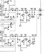
Hi everyone. It's been ages since I dipped my toe in here. My bottom RCA socket is intermittent. I'm sure its where it's soldered into the board. Being really lazy and trying to avoid removing the pcb to solder the back I wondered if anyone can tell me an accessible point on the top of the board, a resistor ect that I can solder a wire link to. I have tried downloading a manual with little success.
Thanks
The problem seems to me is on the RCA socket itself due to loose contacts but not on the soldering. I suggest you just change the socket for peace of mind. It is dead easy.
Hi,
Hi, I am just trying to put together 5V LM317 regs with LEDs. Previous posts suggested measuring each LED to get 3.7- 3.8 voltage drop with two green in series (see below). But I am not sure how to measure each LED. Doesn't the voltage drop vary with the current? I don't want to test them when they are in my CD63. Henry
Originally Posted by Malefoda
Hello folks,
On a LM317 reg, I have tried to change the R to ground for 2 green Leds, it's lovely but shows 5.45V instead of 5.0 with the 365R. Is it normal and subject to lower when loaded or I've missed something?
I also wonder if I can power some IC (DAC) pins like analog ones with that 5.45V led-reg and digital with resistor one at 5.05V.
In worst case I'll keep it for an IC with only one PS pin.
Thanks,
Matthieu
The forward voltage of green LEDs is often as high as 2.1V. So two of them plus the 1.2 - 1.25V of the LM317....
The best way is to buy a bag of LEDs and measure them, then pair them up.
The last bag of LEDs I bought for this purpose I ended up with pairs of red and green. You need a total of 3.75 - 3.8V for the pair.
If you change one of the green for a red you'll probably be fine.
Why not just remove the board? It takes a screwdriver and all of 5 minutes, and then you can bask in the satisfaction that the job was done properly.
Hi guys!
Trouble brings me back, sadly.
My players started to be unable to play a full disc, I've seen the issue earlier but had not time to fix it.
The flip/flop board I have at driver's IC made this fault when pushed a bit down, kept playing when pulled up. Sounded like a dry joint, so I've redone it yesterday and no luck, the same. Went on pushing gently the onbaord regulator, and fault came & went.
Second work then, removed that flip flop board.
Too messy, I've tried to unsolder and redo it... but that was a hard time, chip got hot, I got tired... back in the player. No more anything, no more focus or turn... I guess no more clock there. And too tight to dare touch it now...
Anyway I wonder if I feed the clock on the right pin, it's on 19 XtalI, resistor and caps removed. I had a 1M smd cap between XtalIn and out (19-18), was it mandatory? It played a bit without since I've lost it...
Can anywone confirm that?
I'm good for a new clock, I don't have time and patience (I've blown my amp and messed with my speakers's XOs also... ) for a new flip flop, so I'll just buy a new clock. Advise anyone? Ray's Flea kit? AudioGD's clock? Another new kid on the block?
Thanks,
a musicless Matthieu (almost dying!)
Attachments
+1. Ray also gives you excellent advices when needed.You can't go wrong with a Flea kit (or two).
A dying audiophile, we can't have that! 😉
Pin 19 is the right pin, so that's not the problem. Have you kept the original resonator? You could put it back and see if that solves the problem. It's probably a broken track or some other bad connection.
Pin 19 is the right pin, so that's not the problem. Have you kept the original resonator? You could put it back and see if that solves the problem. It's probably a broken track or some other bad connection.
Hi,
But I am not sure how to measure each LED.
take a terminal block and wire the 2 meter probes into one side, on the other side connect a voltage source (at least 5v) with a resistor in line on the + side.
Then you can just touch your led legs on the screws on top of the terminal block to make a circuit and you'll get the voltage reading on the meter. Make sure you put them the correct way round or you will blow them.
Regards
Pete
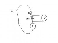
Hi Pete,
I monitored the voltage across the LEDs and monitored the current with a second multimeter (see attached). I used a 9v battery and a range of resistors from 360R to 5.4K. The voltage drop for two green LEDs in series is:
4.6V at 26mA
4.0V at 7.2mA
3.8V at 1.8mA
3.7V at .95mA
Am I doing something wrong? What I need to know is what current range to expect for servo, decoder and dac. I guess I should figure it out from the chip datasheets?
take a terminal block and wire the 2 meter probes into one side, on the other side connect a voltage source (at least 5v) with a resistor in line on the + side.
Then you can just touch your led legs on the screws on top of the terminal block to make a circuit and you'll get the voltage reading on the meter. Make sure you put them the correct way round or you will blow them.
Regards
Pete
Attachments
You can use 4.0V as a practical value. Current through the LED will be somewhere between 5 and 10mA if used with an LM317.
Regards,
Ray
Regards,
Ray
When you use the two diodes to set the 317 output voltage, they are fed from a near-constant current, which is 1.25v/Rset (the resistor between the Vout and Vadj pins sees 1,25 across it). So use a 560 or 680ohm resistor for these LEDs and don't worry about absolute DC voltage - its not important, providing you hit the target +/-5% (i.e. within the fed IC's datasheet tolerance)
NB it turns out there are green leds and green leds, and some newer ones use slightly different forumulation and so have higher dynamic reistance. looks like these are the one you have - but don't worry about it.
NB it turns out there are green leds and green leds, and some newer ones use slightly different forumulation and so have higher dynamic reistance. looks like these are the one you have - but don't worry about it.
A dying audiophile, we can't have that! 😉
Pin 19 is the right pin, so that's not the problem. Have you kept the original resonator? You could put it back and see if that solves the problem. It's probably a broken track or some other bad connection.
Hi Ray & fellows,
sadly the OEM cristal is long gone. And yes sounded like a solder joint but on my flip flop wich I admit was badly done at that time. BTW, the Flea and the Tentlabs XO may save me 🙂
Thanks Ray and Martin,
if I understand this right, 680ohm will give 1.8mA (1.25/680). So the voltage drop will be about 3.8V according to my tests (post 20610). I'll give it a go!
Henry
if I understand this right, 680ohm will give 1.8mA (1.25/680). So the voltage drop will be about 3.8V according to my tests (post 20610). I'll give it a go!
Henry
When you use the two diodes to set the 317 output voltage, they are fed from a near-constant current, which is 1.25v/Rset (the resistor between the Vout and Vadj pins sees 1,25 across it). So use a 560 or 680ohm resistor for these LEDs and don't worry about absolute DC voltage - its not important, providing you hit the target +/-5% (i.e. within the fed IC's datasheet tolerance)
NB it turns out there are green leds and green leds, and some newer ones use slightly different forumulation and so have higher dynamic reistance. looks like these are the one you have - but don't worry about it.
Originally Posted by ray
You can use 4.0V as a practical value. Current through the LED will be somewhere between 5 and 10mA if used with an LM317.
Yep, that's right. However, the LM317 needs a minimum load current of 5 - 10mA. Usually, this condition is met by using a 120 ohm resistor for Rset so you don't have to worry about this anymore. To make sure your LM317 is regulating properly, you can add a 560 ohm resistor at the output.
Also, don't get hung up with only using green leds, different colours will have different voltages, most of my regs end up with a combination of different colours (though I normally just buy red, green, yellow)
Also I only ever check the voltage of leds individually then just find a pair that add up to the required value, as noted above 5v +/- 5% isn't going to do any harm, if you look at the spec of the chip that you're feeding they will always have at least that amount of tolerance.
Nice diagram, btw, very useful.
Regards
Pete
Hi Pete and Ray,
I probably should have stuck with Ray's standard version and not tried the one with the fancy bright lights! At least I've learned something about LEDs 😀. Is the reason for using LEDs here because they have dynamic resistance and will deaden fluctuation in the current? (Or is it just because they are pretty?)
So, I shouldn't go too low with the current. I will get 5.2mA with 240ohm resistor and 10.4mA with 120ohm (between Radj and the output). I have bought some amber and red diodes and will have a play over the weekend. I am aiming for 3.75 voltage drop with one of these two current settings. I know it doesn't have to be too precise, but as I am going to make a dozen of them I would rather they were all as identical as possible. Ray, does the 560R resistor at the output go to ground?
Also, I found these boards at digikey that seem like just the thing for making miniregs. And as I don't have a dremel, these inexpensive cutting discs work really well on my drill to cut them down to size. (I have spent many frustrating hours hacking away at PCBs with various saws and clippers ). I am careful to avoid the dust.
Henry
I probably should have stuck with Ray's standard version and not tried the one with the fancy bright lights! At least I've learned something about LEDs 😀. Is the reason for using LEDs here because they have dynamic resistance and will deaden fluctuation in the current? (Or is it just because they are pretty?)
So, I shouldn't go too low with the current. I will get 5.2mA with 240ohm resistor and 10.4mA with 120ohm (between Radj and the output). I have bought some amber and red diodes and will have a play over the weekend. I am aiming for 3.75 voltage drop with one of these two current settings. I know it doesn't have to be too precise, but as I am going to make a dozen of them I would rather they were all as identical as possible. Ray, does the 560R resistor at the output go to ground?
Also, I found these boards at digikey that seem like just the thing for making miniregs. And as I don't have a dremel, these inexpensive cutting discs work really well on my drill to cut them down to size. (I have spent many frustrating hours hacking away at PCBs with various saws and clippers
). I am careful to avoid the dust.Henry
Yep, that's right. However, the LM317 needs a minimum load current of 5 - 10mA. Usually, this condition is met by using a 120 ohm resistor for Rset so you don't have to worry about this anymore. To make sure your LM317 is regulating properly, you can add a 560 ohm resistor at the output.
Attachments
The LEDs have a low internal resistance, they are essentially diodes in forward conducting. They are relatively low noise (like anything with a low impedance) so a cheap voltage reference, better than zener diodes! Plus, the colored light looks very audiophile 🙂
The 560 ohm resistor goes to GND indeed, but is only needed if the no-load current is lower than 10mA. So if you use 120 ohm for Rset, you don't need it.
The 560 ohm resistor goes to GND indeed, but is only needed if the no-load current is lower than 10mA. So if you use 120 ohm for Rset, you don't need it.
Puff of grey smoke!
Hi, I have managed cook something. I just did Ray's PS mods:
Power supply
C801/802 22n cer. 22n/MKS Wima
C803/804 470u/35V 2200u/35V Panasonic FC 303-6455
C805/806 470u/16V 1200u/16V Panasonic FC 303-6182
C813 4700u/16V 4700u/16V Panasonic FC 303-6212
C814 1000u/16V 3300u/16V Panasonic FC 303-6200
C815 3300u/6,3V 4700u/6,3V Panasonic FC 303-6005
D801...804 S5688G BYV95A/11DQ10 schottky
D811...814 S5688G BYV95A/11DQ10 schottky
Q801/802 78M12/79M12 LM317/LM337 (15V Raygulators)
Q811 7805 LM340AT-5,0 NSC 412-703
When I plugged it in there was a slight buzzing noise and a grey puff of smoke from the area of the IC Chip and the display was not working. 😱
I unplugged it after just a few seconds, and after going over everything realized that I had wired the tantalum capacitor for the LM337 reg with the wrong polarity. I fixed that and now it spins discs but there is no music - just lots of white noise.
Any ideas?
Henry
- Home
- Source & Line
- Digital Source
- Marantz CD63 & CD67 mods list