As Ray wrote it on his page : Conrad 12V Linear Power Supply Board PCB Pre-Assembled from Conrad.com
The PFM Flea
The PFM Flea
Thanks Luke, I have been so busy going through his PDF and searching the internet to think of going back to look on the flea page.
The question is now though, how has he modified it to get 18volts, as it is a 12 volt supply.
now I'm even more puzzled
Looked at the schematic in the Flea, I'm afraid I now little about electronics, I have a book but just haven't got around to reading it, I know a voltage regulator needs a input voltage greater than output voltage and the diodes are there to turn the AC to DC by only letting the current flow one way. As AC is changing direction at 50 times a second, logic tells me that the current supplied to the regulator will flow alternately 50 times a second through D1 and D2 and never at the same time so even though they are in parallel the voltage will remain at 15 volts.
That is what logic tells me, I have an obvious lack of understanding on the subject, I assume then that the voltage supplied to the regulator is therefore 30 volts.
Timjar, AC/DC conversion usually increases the voltage. For example, my 12v toroidal transformer gives out 12v AC, but once this is converted to DC with a diode rectifier circuit, it ends up somewhere around 18v DC.
Thanks for that dwjames, it begins to make a bit more sense now, I have been reading posts in this thread regarding voltages supplied, and have thought I had read an earlier post that their TX was a lower voltage.
I have just completed going through Rays PDFs for mods on the CD63II and CD63II KI, I have made my list of parts for ordering, but in the 63 KI pdf the Epocos part at U196 521-2870 and the parts for C513 and C119 969-5532 are no longer on Farnell site.
Also when he next comes online, are those ceramic beads 242-500 really that much more suitable than the ones that only cost 2-5p each , also what capacitors does he recommend instead of Black gates.
That's unfortunate, anything I can do to help?
Thanks Ray, I'll get back to you. I'm trying to get my player in a state where it's easier to work on.
What's the best way to ground my 5v regs? They were each grounded to the negative pin of each local decoupling cap, but I don't like all the wires under the board. Should I ground to top screen or wire to star?
The question is now though, how has he modified it to get 18volts, as it is a 12 volt supply.
Here's what you need to build the same 18V psu Ray has advised :
Conrad part number :
1x psu : 190835-62
4x diodes : 155460-62
1x 18V reg : 179256-62
1x cap : 421975-62
you just need to swap the original parts (diodes, reg and cap) with those one, and you're done.
Just been looking at CD transports for CD63/67, and on one site it mentions that before installation you must "remove protection points",
Is there something that should be removed on the laser assembly before trying to use?
Is there something that should be removed on the laser assembly before trying to use?
Just been looking at CD transports for CD63/67, and on one site it mentions that before installation you must "remove protection points",
Is there something that should be removed on the laser assembly before trying to use?
Yes, small metal clip on the end of cable on the left.
Attachments
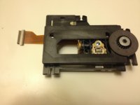
Only the one on the ribbon cable then, nothing on the laser assembly itself?
Nothing else.
Here's what you need to build the same 18V psu Ray has advised :
Conrad part number :
1x psu : 190835-62
4x diodes : 155460-62
1x 18V reg : 179256-62
1x cap : 421975-62
you just need to swap the original parts (diodes, reg and cap) with those one, and you're done.
Thanks,
parts are ordered
After a year in sickbay, it turns out my tech actually managed to source the last NOS laser assembly in Canada. So I now have a working cd-63 KI. At least I will when I get a chance to pick it up. 🙂
So now I have to make it sound good!
So now I have to make it sound good!
Hi sorry first post so forgive me.
I picked up a CD63 K1 signature today. It has one annoying thing. When I press the eject button it seems to suffer from switch bounce and the drawer comes out and immediately goes back in sometimes. I have no remote. I'm guessing this would have an eject button and I would be able to use this if I had one.
Anybody come across this?
Thank you.
It's probably the end switch that detects if the drawer is fully out. Give it a good clean with some contact cleaner and it should be fine. The switch is located at the front of the transport, on the right-hand side.
It could also be that connector JM02 is not properly seated or needs to be cleaned.
It could also be that connector JM02 is not properly seated or needs to be cleaned.
I often find this fault is caused by the eject button itself. It double bounces and tells the drawer to go back in (or out). The one on the mech is pretty bullet proof on these. I have only ever known one fail.
You will need to remove the front pcb and fit a new switch.
regards
Brent
You will need to remove the front pcb and fit a new switch.
regards
Brent
- Home
- Source & Line
- Digital Source
- Marantz CD63 & CD67 mods list