spiro, I have tried your methods but contradictory to what you said, rod elliott said that adding more turns = more wire = more resistance = more heating = less efficient. and also, the rails WILL sag and you get lower output voltage at high power levels.
in my SMPS, I used 6+6 turns in the primary. the good people who know what they are doing use 4+4 turns. I used 6 since that is the least amount of turns I could fit in before spikes and ringing start to kick in, possibly making the core as saturated as possible. (the waveform is not perfect, I have slight but allowable ringing but no high voltage spikes. testing is done at 13.8V input, I raise it up to 15V with no additional ringing or spikes.)
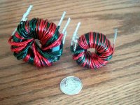
my core is about 1.5" (38mm) external diameter, with atleast 1.2cm^2 of core area. primary is made with 3X 1mm copper wire, secondary is made with 2X 1mm copper wire. it powers two P3A amps at +/-35V rails.
rails sag because of input power cable resistance. if you keep a regulated input to the SMPS, the rails are rock solid.
in my SMPS, I used 6+6 turns in the primary. the good people who know what they are doing use 4+4 turns. I used 6 since that is the least amount of turns I could fit in before spikes and ringing start to kick in, possibly making the core as saturated as possible. (the waveform is not perfect, I have slight but allowable ringing but no high voltage spikes. testing is done at 13.8V input, I raise it up to 15V with no additional ringing or spikes.)
my core is about 1.5" (38mm) external diameter, with atleast 1.2cm^2 of core area. primary is made with 3X 1mm copper wire, secondary is made with 2X 1mm copper wire. it powers two P3A amps at +/-35V rails.
rails sag because of input power cable resistance. if you keep a regulated input to the SMPS, the rails are rock solid.
Help for creat gerber file
Hi All,
Hey Any body help me to creat gerber file from .pcb file. wich downloaded from valveaudio site
Hi All,
Hey Any body help me to creat gerber file from .pcb file. wich downloaded from valveaudio site
Bought transformer cores...
Bought some cores off of eBay. Might not work, but then again it might...
eBay cores
I'm not sure how much power these could be good for, but I'm willing to give 'em a try. Gotta be better than the scavenged PC power supply cores that I've blown up in the past. 🙂
Well. I think it looks promising. It would be really cool if these work for an amp SMPS, but even if it will just give me a few mA at +/-15VDC I'll count it as a success. (If it'll give me 5A at +/-35VDC, I'll be beside myself.)
Supraguy-if it does work out well be sure to make a site with metatags so that people who search for DIY SMPS can find it 🙂
the cores (used as a pair) will be good for about 150 to 200 watts SMPS. even if crudely designed. I suggest around 6-8 turns per primary and about 35-50kHz. give it a try.
Just be sure to use a cardboard former to wind on. Ferrite is so brittle, I've broken every E-core I've tried to wind. I have had some success gluing them back together with epoxy though.
The transformers I got from Zagsrule (on this forum) are awesome and he had a bunch of them to sell, but it seems as though he's dissapeared.
The transformers I got from Zagsrule (on this forum) are awesome and he had a bunch of them to sell, but it seems as though he's dissapeared.
Yeah, I was looking to get some from him...
Mike: Sure. But considering how badly my website has been neglected for the last few years, don't hold your breath. It's more likely that some info will appear elsewhere, but I'll get as complete a write-up on it as I can.
And yes, I'm planning to wind on a cardboard tube and slip it together. (I'm perfectly aware that I need a pair to make a transformer. -- not quite THAT much of a noob.) I have a couple of ideas about how to hold the 2 halves of the core together, I don't want to put too much stress on it, but I want it held together, too. A Nylon tie strap to the project case should do the trick, I think, but if there are better suggestions, then by all means...
I've also got those Maxim chips to do a small +/-15V power supply, I'll attempt to make a +/-35V supply with these. If nothing else, it'll be interesting.
(I'm perfectly aware that I need a pair to make a transformer. -- not quite THAT much of a noob.)
hehe, just making sure. 😉
😀 as for the fastening of the cores, I only tape it together. but I do that to cores smaller than 1.5 inch square. I haven't used a big double E core. I use toroids for big ones.
if you're going to tie it with nylon strap, I think it would be better to tie it on the PCB of the powersupply. so that it is nearer to the circuitry. Unless you're out of board space.
I'm here guys. Sorry to have seemed to "dissappeared" I was really busy for a while.
Prices were $17 for large units and $13 for small units. If interested feel free to e-mail me. I have a large quantity available and they do look and perform great! 🙂
They designed to be run in regulated mode (where voltage feedback goes back into the PWM controller and PWM is adjusted to keep output voltage constant). The large unit was wound to put out +/- 35V from 10-16V supply. There are dual secondaries and dual primaries that have massive leads....the big unit will supply 500W or so with no sweat, I have a few running in my car right now with no problems, power supply based on the TL598 though. I am not sure how the TL494 and 598 differ though, any of you know off the top of your head?
-Matt Aurand
matt.aurand@anderson-aurand.com
Attachments
I repaired a large 4 channel Phillips car amp, it seemed to have no IC's (All discrete components). it is only 2 years old, So curiosity get the better of me and I got out the CRO, And as I assumed the transformer was fed by a constant 50-50 duty cycle even at no load. And yes the Amp is working perfectly, supply rails at +/- 25 Volts
Has any one here tried this before?
Is there any disadvantage by using such a simple design??
I have already started designing a PCB for this type of power supply. Am I wasting my time???
Also the zagisrule! transformers look good, i will be ordering some soon. I may make MY PCB to suit this core.
Has any one here tried this before?
Is there any disadvantage by using such a simple design??
I have already started designing a PCB for this type of power supply. Am I wasting my time???
Also the zagisrule! transformers look good, i will be ordering some soon. I may make MY PCB to suit this core.
The frequency range for these would be around 50khz minimum, but 75khz or so will give you more efficiency. At 75khz they are about 85% efficient.
You have mail Spiro.
-Matt
You have mail Spiro.
-Matt
Matt, I'm running my small Transformer I got from you at 45khz unregulated. These transformers are so much more forgiving than the ones I wind myself. I just threw it on the board and it was solid as a rock. No tweaking and no heat and no noise! My home wound cores would sing an eirie whine similar to a horror movie soundtrack.
Glad to hear it 2pist 🙂
I was thinking today about offering a kit including all parts (PCB, MOSFET's, transformer, IC, misc components) for a SMPS. It would be easier for many here to make their GC car amps when all they have to do is assemble a kit and be guranteed a working design.
Would anyone be interested in something like that?
-Matt
*&%$# Yeah!
I've been driven nuts looking for power supply parts. If I could get a kit, I'd be all over that, provided that the price was "reasonable."
I'm not against you making money on the design and distribution of a kit, but I don't exactly want to put your kids through college. (I have my own to worry about.)
I'd be up for a decent kit of parts
Just being able to start from a known good design would be great, if modular was an option so much the better, ie more or less power, perhaps +/-25v or +/-40, 5amp or 10amp etc. You probably know better than I whats reasonable, and doable in the context of the parts you have access to.
Stuart
Just being able to start from a known good design would be great, if modular was an option so much the better, ie more or less power, perhaps +/-25v or +/-40, 5amp or 10amp etc. You probably know better than I whats reasonable, and doable in the context of the parts you have access to.
Stuart
to lower the end price of the kit (if you do get to go with your plan), you could supply only the hard to find parts like the MOSFETS, transformers etc and leave the customer to buy the easy ones like resistors, caps etc. just a suggestion. 🙂
Hi all
I agree, leave the everyday components out of the kit,those are easy to get.
Youd need a nice site,with exposure and advertising and linkage.
Shipping overseas would bump up the price-not a problem for locals tho!
and i think anything over 100w is worth building, because thats about 6db over headunit power.
I presume above that power, beefier output transistors etc ,transformers push up price.
Bear in mind ONLY MJ15004/3s and 3005/2955 pairs are available in some countries like here (NZ!)
Cheers!
FYI: I also have a large quantity of the IRFP054N here in stock, they are perfect for SMPS, again they are running in my car. I'd be willing to get rid of these things too at a very reasonable price.
I will think on a kit and see what I come up with. It sure would make it much easier for "Joe" to assemble a car amp 🙂
Thanks for the input!
-Matt
I will think on a kit and see what I come up with. It sure would make it much easier for "Joe" to assemble a car amp 🙂
Thanks for the input!
-Matt
Hey guys,
I seem to have had a problem with my e-mail (@anderson-aurand.com), I replied to inquires using a different address a few minutes ago...sorry for the delay!
-Matt
I seem to have had a problem with my e-mail (@anderson-aurand.com), I replied to inquires using a different address a few minutes ago...sorry for the delay!
-Matt
How to build Ferrite core transformer for SMPS?
I want know how to build ferrite core transformer?
How wire gauge i have used in this smps ferrite core?
How many turns I have to used for primary and secondary?
specially i want to know how to wire turn on the ferite core?
I also see some pic in the many threasd replly but i did not guessess. i have littlebit knowledge about transformer.
Regards
Robin
- Home
- General Interest
- Car Audio
- Making car amplifier SMPS with tl494 + DC Protection