Playing with Nelson Pass MicroCap-simulation
This sunday morning I was playing with MicroCap and LTSpice Nelson Pass is offering to us. Thanks! Big fun!
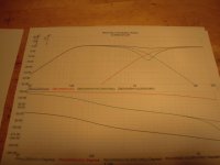
I want to get a bandpass between 80 Hz and 2500 Hz (for the mid-bass). Playing around to make the lower crossover point switchable (50 Hz /65 Hz/ 80 Hz / 100 Hz) by changing/ switch C1.
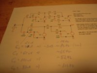
The highpass from 2000 - 2500 Hz up for the tweeter. I forgot to make screenshots. My present values are:
Highpass:
C4 4nF
C3 4nF
R1/ R2 18kOhm
R12 0K
C15 0nF
R9/R10 100 Ohm
C16 3nF
R11 1kOhm
Low / Bandpass:
C1 switchable 100nF = 52 Hz (-3dB)
60 nF = 65 Hz
47 nF = 80 Hz
33 nF = 100 Hz
C2 100nF
R6 47 kOhm
R7 15 kOhm
R3/R4 10 kOhm
C13 15 nF
C14 10 nF
Till now - only simulated! Need some new caps....Sorry for the bad pics.
This sunday morning I was playing with MicroCap and LTSpice Nelson Pass is offering to us. Thanks! Big fun!
I want to get a bandpass between 80 Hz and 2500 Hz (for the mid-bass). Playing around to make the lower crossover point switchable (50 Hz /65 Hz/ 80 Hz / 100 Hz) by changing/ switch C1.
The highpass from 2000 - 2500 Hz up for the tweeter. I forgot to make screenshots. My present values are:
Highpass:
C4 4nF
C3 4nF
R1/ R2 18kOhm
R12 0K
C15 0nF
R9/R10 100 Ohm
C16 3nF
R11 1kOhm
Low / Bandpass:
C1 switchable 100nF = 52 Hz (-3dB)
60 nF = 65 Hz
47 nF = 80 Hz
33 nF = 100 Hz
C2 100nF
R6 47 kOhm
R7 15 kOhm
R3/R4 10 kOhm
C13 15 nF
C14 10 nF
Till now - only simulated! Need some new caps....Sorry for the bad pics.
Attachments
Last edited by a moderator:
I'm late to the party again. I just ordered the Basic kit from the DIYaudio store.
Would one of you who has built that pcb give me some approximate dimensions for the board? I'm sure it here somewhere but I have probably skimmed over it.
Thanks.
Jac
Would one of you who has built that pcb give me some approximate dimensions for the board? I'm sure it here somewhere but I have probably skimmed over it.
Thanks.
Jac
I just tested it, and it worked for me. It's a zip file containing the two sims. Can someone else confirm?firstwatt link doesn't work
tnx
Last edited by a moderator:
The one in Post #119 doesn't work. It goes directly to the .CIR file. Where is the other First Watt link?
That's the one I can't get, cir file, tried with different pc's . on one pc says can't download on other one says file missing.
The one in Post #119 doesn't work. It goes directly to the .CIR file. Where is the other First Watt link?
I was using the one you get from the DIY page at First Watt, but the above post link is fine also.
Last edited by a moderator:
Mr Pass, do you think is appropriate for me to post the modifications I made on your schematic and simulation adding the midrange filter for a 3 way crossover?
Mr Pass, do you think is appropriate for me to post the modifications I made on your schematic and simulation adding the midrange filter for a 3 way crossover
Feel free. Siegfried clearly wanted information to be public on this, and posting yours will add to the conversation.

Last edited by a moderator:
The crossover points i need are configured but ; they can easily go changed ; maybe a way to modify those crossover points by using a potentiometer or fixed resistors would be great. I also found that in simulation AC->Slider can create a pot out of any resistor allowing a almost realtime curve update.
see the archive here
Edit:
and screen shot; see sliders on right side 🙂 :

see the archive here
Edit:
and screen shot; see sliders on right side 🙂 :
Last edited:
First order xover changes question
I would like to try a first order xovr setup and would like to know how to do that. I know the high and low sections have 2 pole filters for a 2nd. order implementation, but I am not sure which capacitors or resistors to bypass in each section to accomplish a 6 db/octave filter for both high and low pass sections.
And also, a comment or maybe a question I Have been experimenting with the phase connection to my subwoofers. I started with inverted woofer connections but last night I changed the connection to "normal" and it seems to me the that the blend is much better ?.. So now, supposedly the woofers are out of phase. Both the mains and sw's are open baffle - Spatial M4's and a diy Ripoles. Thanks!
Last edited by a moderator:
You could maybe get away with simple passive RC-filters in front of your power amps.
That was the principle behind the Tannoy XO5000 powered xover with the passive two way modules...
Thanks, I understand your idea, but I am referring to the lx-mini implementation. Upon looking into the B4 manual in the FW site I think I might seen how to do it.. The remaining question is regarding my observation about the phase issue rendered in my post above.
Av. Of course, you will need the other parts of the design as well. Nevertheless it should be easy to reduce the filter to first order.
- Home
- Amplifiers
- Pass Labs
- LX-mini Crossover Article