Those values are correct. For R17-20 and R39-42 we are simply loading the output
of the circuit to ground. When these parts were tested, this gave the lowest thd
values. It's a subtle difference. Some value is necessary, as they provide the
DC reference voltage for the next stage.
of the circuit to ground. When these parts were tested, this gave the lowest thd
values. It's a subtle difference. Some value is necessary, as they provide the
DC reference voltage for the next stage.
Those values are correct. For R17-20 and R39-42 we are simply loading the output
of the circuit to ground. When these parts were tested, this gave the lowest thd
values. It's a subtle difference. Some value is necessary, as they provide the
DC reference voltage for the next stage.
Thanks, the difference between the values seemed worth asking about.
I bought one of the board + JFET kits when they were first released in the DIYAudioStore with the intention of using it to make a crossover for a PAP TrioTB copy.
Also picked up a Mesmerize B1 kit at the same time, haven't decided if it will be used or not. I noticed on the previous page that the B1 triode was given a thumbs up.
Here goes, trying to keep the question simple. Not certain if this is the best product to use for what I was considering building.
Right now, for amps currently in use I have a pair of F4 monobocks with voltage gain coming from 6SL7's.
Can I use a B1 in some form, then after the buffer is where the analog crossover is used(?), before the 6SL7 voltage gain stage and have the F4's power the woofers, then some smaller amp (I have an ACA that has not been built, but want to try something with tubes, endless options) to power the full range?
Would it be more sane (it's August in Texas) to use a chip amp to power the woofers, and for the full range use dual mono (single amp boards) F4's with a more sane gain from 6SN7 (10V / 20dB) instead of the higher gain of 6SL7 (31V / 29dB)?
I would be going from speakers with are not that efficient (88dB?) to something that is much more efficient. The maximum level at listening position is 95dB with my current setup (measured with a phone app, not an actual microphone).
in my short knowledge, if you don't need multiple input selector, main purpose of mezmerize then skip it. so your chain will be 6SN7 -> LXmini -> F4 & other amplifier. otherwise put mezmerize before 6SN7.
regarding B1 (original or Korg) usage as buffer, i don't think it will be usefull in your chain because LXmini and F4 already has input buffer.
regarding B1 (original or Korg) usage as buffer, i don't think it will be usefull in your chain because LXmini and F4 already has input buffer.
Last edited:
Actually the LXmini ACN does not have input buffers and a B1 (either DIYPass or Mesmerize) would be useful to prevent loading of any tube amplified source just ahead of it. I have had good results in two different biamplified setups:
1) Source>B1>LX mid/hi>B1 Korg>F6>spkrs + LX low>SS AB amplifier>spkrs
2) Source>B1 Korg>LX mid/hi>F6>spkrs + LX low>SS AB amplifier (attenuated)>spkrs
If you use tubes for gain, look to possibly reducing 2nd harmonic signature of B1 Korg if it is also in the signal chain.
I found system sounds better to run LXmini ACN input pots wide open if bass amp has input attenuators to match the lower mid/hi amp gain
Attachments
Last edited by a moderator:
I am a beginner. I have a question. I want to use the ACN-basic kit from diyaudiostore for my 2way-speaker. The speaker is SEAS's Loki-Mk3 and it's crossover is "2nd order symmetrical with a 2.9 kHz crossover frequency SEAS Loki MkIII
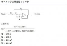
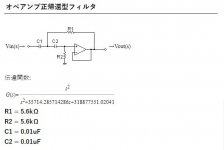
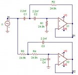
I have no knowledge of calculating the C and R values to replace this passive crossover with an active crossover.So I asked Google and found the filter calculation homepage (I'm sorry, it's Japanese). (サンプル)オペアンプ正帰還型ローパス・フィルタ計算ツール In this page, if I enter the cutoff frequency and the quality factor "Q", the C and R values required for the "op amp positive feedback type" HPF / LPF are calculated.
Question 1: Can I apply this "op-amp positive feedback type" calculation to ACN calculation? I entered a cutoff frequency of 2.9kHz and Q = 0.5 (2nd order Linkwitz–Riley in my understanding) on this page, and obtained HPF / LPF values of C: 0.01uF and R: 5.6kohm(Pic.1,2).
All C and R have this same value.
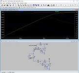
Question 2: Are these C and R values normal? I calculated the above values with LTspice (I have no experience).
Question 3: Are the results correct?
Any advice and opinions are welcome. Sorry about my terrible English.
I have no knowledge of calculating the C and R values to replace this passive crossover with an active crossover.So I asked Google and found the filter calculation homepage (I'm sorry, it's Japanese). (サンプル)オペアンプ正帰還型ローパス・フィルタ計算ツール In this page, if I enter the cutoff frequency and the quality factor "Q", the C and R values required for the "op amp positive feedback type" HPF / LPF are calculated.
Question 1: Can I apply this "op-amp positive feedback type" calculation to ACN calculation? I entered a cutoff frequency of 2.9kHz and Q = 0.5 (2nd order Linkwitz–Riley in my understanding) on this page, and obtained HPF / LPF values of C: 0.01uF and R: 5.6kohm(Pic.1,2).
All C and R have this same value.
Question 2: Are these C and R values normal? I calculated the above values with LTspice (I have no experience).
Question 3: Are the results correct?
Any advice and opinions are welcome. Sorry about my terrible English.
Attachments
Last edited by a moderator:
Any advice and opinions are welcome. Sorry about my terrible English.
Congratulations. All looks good. Actual R values for C=0.01 is 5.488K ohms but the standard value of 5.6K ohms is certainly close enough. I recommend 1% tolerance metal film resistors and 2.5% tolerance film capacitors.
Keep in mind that the PCB layout for the DIYstore ACN is for cascaded filters specific to the LXmini loudspeaker. You will not use filter 1 of the low pass section and will not use filter 2 of the high pass section. These unused filters are easily bypassed.
Personally, I find this crossover sounds best with the 25K input trimmers set to full input and attenuation used on one of the amplifier inputs if level balancing between HI and LO is required.
If you will be feeding this crossover with a tube preamplifier that does not work well into the 12.5K ohm effective input impedance, you may want to consider re-purposing the unused filter sections as unity gain buffers and deleting the input pots. Easily done in the LO section but requires some fancier trace and jumper work in the HI section to get section 2 in front of section 1.
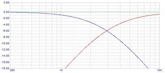
That looks a little off - the response would want to be -6 dB at the crossover point for a flat sum.
This filter will give a flat sum with one driver phase inverted. (edit) my error, I misread the scale on your resp graph.....
This filter will give a flat sum with one driver phase inverted. (edit) my error, I misread the scale on your resp graph.....
Attachments
Last edited by a moderator:
Given the large range of possible capacitor/resistor combinations, it never ceases to amaze me how you seem to so easily get so close using off the shelf capacitor and resistor values. Given a nominal 10K resistor starting value, is it better to go higher than lower? What do you consider the value limits in this topology and pros/cons of say, 5K vs 30K?
Last edited by a moderator:
easy , he's Papa.... it never ceases to amaze me how you ......

think Rin of stage.........say, 5K vs 30K?
Last edited by a moderator:
easy , he's Papa
think Rin of stage
So, it seems better to go up from 10K when matching R value to a standard C value but probably not go above 50K
The Fets don't care much, but as you go up there is more opportunity
to pick up noise radiated from RF and power sources.
to pick up noise radiated from RF and power sources.
LX mini crossover in 3 way system
I hoping to get some guidance on how to configure the LX-mini kit as a 3 way crossover in a speaker system I'm working on.
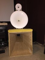
When done it will be an active 3 horn system plus a pair of powered sub-woofers below 100 Hz
An early, wood glue barely dry, work in process picture is below
I already have a pair of the LX-mini crossover kits and would like to use a single stereo kit on each side but configured as a mono crossover with Low Mid and High outs.
I thought I remembered seeing something on this in this thread but after much searching I decided to cry for help😕
My ask is for some guidance on how to configure / connect it as a 3 way.
Once I have the basics I can modify the micro-sim model to dial in the component values.
Right now I am using:
An old Paradigm active low pass crossover to the subwoofers @ 100 Hz
Above 100 Hz runs through a Mini-DSP 2x4HD which is great for tuning with REW to get you in the ballpark.
I also like the mini-dsp for correcting rooms modes down low but not really a long term solution for higher up.
- Midbass horns via HD 2x4 channel 1&2 as a second order low pass at 500 Hz (with a 20 Hz low cut shelf to limit excursion)
- Midrange horns via HD2x4 channel 3&4 as a second order high pass at 500 Hz (with inverted connection to midrange horn driver).
- High horns are currently via a passive first order filter @ circa 3.5 kHz.
On channels 3&4 I also did a high shelf with a +5 dB boost above 3.5 kHz as a quick and dirty way to level match even through a passive crossover.
Although it is a complete kludge, it actually worked better than I thought it would and well enough to get me in the ballpark for the mid to high crossover point.
I would like to end up with the LX mini crossover configured something like:
- Mid bass horn: Low pass @500 Hz
- Midrange horn: High Pass @ 500 >> Low Pass @ 3.5 kHz
- High horn: Low pass @ 3.5 kHz
The mid bass horn rolls off below 100 Hz as predicted by Hornresp so I plan to relocate the mini-dsp to do room correction / low pass only below 100 Hz to the subwoofers.
Any guidance, suggestions or breadcrumbs would be most appreciated.
Best Regards,
Berd
I hoping to get some guidance on how to configure the LX-mini kit as a 3 way crossover in a speaker system I'm working on.
When done it will be an active 3 horn system plus a pair of powered sub-woofers below 100 Hz
An early, wood glue barely dry, work in process picture is below
I already have a pair of the LX-mini crossover kits and would like to use a single stereo kit on each side but configured as a mono crossover with Low Mid and High outs.
I thought I remembered seeing something on this in this thread but after much searching I decided to cry for help😕
My ask is for some guidance on how to configure / connect it as a 3 way.
Once I have the basics I can modify the micro-sim model to dial in the component values.
Right now I am using:
An old Paradigm active low pass crossover to the subwoofers @ 100 Hz
Above 100 Hz runs through a Mini-DSP 2x4HD which is great for tuning with REW to get you in the ballpark.
I also like the mini-dsp for correcting rooms modes down low but not really a long term solution for higher up.
- Midbass horns via HD 2x4 channel 1&2 as a second order low pass at 500 Hz (with a 20 Hz low cut shelf to limit excursion)
- Midrange horns via HD2x4 channel 3&4 as a second order high pass at 500 Hz (with inverted connection to midrange horn driver).
- High horns are currently via a passive first order filter @ circa 3.5 kHz.
On channels 3&4 I also did a high shelf with a +5 dB boost above 3.5 kHz as a quick and dirty way to level match even through a passive crossover.
Although it is a complete kludge, it actually worked better than I thought it would and well enough to get me in the ballpark for the mid to high crossover point.
I would like to end up with the LX mini crossover configured something like:
- Mid bass horn: Low pass @500 Hz
- Midrange horn: High Pass @ 500 >> Low Pass @ 3.5 kHz
- High horn: Low pass @ 3.5 kHz
The mid bass horn rolls off below 100 Hz as predicted by Hornresp so I plan to relocate the mini-dsp to do room correction / low pass only below 100 Hz to the subwoofers.
Any guidance, suggestions or breadcrumbs would be most appreciated.
Best Regards,
Berd
Attachments
My ask is for some guidance on how to configure / connect it as a 3 way.
Once I have the basics I can modify the micro-sim model to dial in the component values.
Berd
Berd
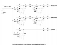
Here is a modified LTSpice Model and printout with your crossover points and component numbering that matches the PCB. It includes a HPF at 100Hz for the low horn. I used standard cap values that got me pretty close using standard resistor values.
If you want to fine tune the filters, you may want to pick up a copy of tubeCAD filter designer - it's only ten bucks.
TCJ Filter Design - Download
This can be a help if you want to plug in different standard caps and see how the resistors come out - I try to stay in the 5K to 25K range of resistance values.
Attachments
AVDGuru:
Thanks very much for the model and the referral to TCJ Filter designer.
I'll play with it a bit and get parts on order.
Berd
Thanks very much for the model and the referral to TCJ Filter designer.
I'll play with it a bit and get parts on order.
Berd
AVDGuru:
Thanks very much for the model and the referral to TCJ Filter designer.
I'll play with it a bit and get parts on order.
Berd
Note: I did not include input trimmers. I found that because there were no input buffers for this board, the crossover sounded best with the 25K input trims wide open. Your results may vary.
Due to the use of 3 inputs in parallel, if you don't have power amp input attenuation for balancing, and you end up adding input trims, you may want to consider upping the trimmers to 50K to raise the effective input impedance your preamp sees from 8.3K to 16.6K. Although solid state preamps should have no problem driving 8.3K.
I have not listened to the circuit without some sort of input loading resistance, in my case 25K trim pots wide open. Something, even 100K, might be necessary to stabilize your preamp. I just don't know for sure.
Papa, so just you know I mentioned you in another thread:
https://www.diyaudio.com/forums/multi-way/339882-crossover-linkwitz-lx521-4.html#post5890524
so you are on the hook . maybe an idea for a Xmass gift?
https://www.diyaudio.com/forums/multi-way/339882-crossover-linkwitz-lx521-4.html#post5890524
so you are on the hook
. maybe an idea for a Xmass gift? Dear Nelson,
I now use miniDSP OpenDRC-DA8 with miniSHARC_4x8 crossover app + FIR plug-in rePhase to feed 3 way analog outs to Pioneer SC-LX87 that drives in a multi-channel mode speaker units in stereo as follows.
Tweeter (over 5kHz): JBL 075 (and Pioneer PT−R5 is driven by a separate stereo amp),
Mid range horn driver (510Hz-5kHz): JBL 2441 with horn,
Woofer (125Hz-510Hz): Fostex FW208N, and
Active super woofer (R+L summed): Pioneer 12 inch woofer + capacitance based mechanical feedback control. The dedicated amp includes a low-pass filter at 125Hz.
I like this system's wide frequency range, high resolution, and generally transparent sound, but when it comes to natural blend of sound, I feel a simpler single-unit based speaker often produces a more natural music with life-like ambiance. The DAC process within the miniDSP is probably responsible for such drawback. In your 14 page document, you explained that your analog crossover was developed to replace a DSP-based active crossover. I suspect that there was a similar reason in this to mine, which please correct me if I am wrong.
In any case I would like to try out the analog crossover of your design, and wonder if you agree that replacing my DSP with your analog crossover is a good and reasonable approach for my purpose. I prefer a 4 ways crossover as described above, but a 3 way solution may be feasible (although if possible I prefer to have a high pass filter at 125 Hz).
If you or someone with a similar experience can give me a guidance, that is very much appreciated.
RY
You don't seem to need the EQ circuits of the LXmini, so maybe an
ordinary flexible crossover would work for you.
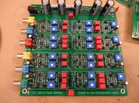
I have a crossover ready for the store which is 6,12,18,24 dB/oct high pass
and low pass for each channel, and this might be appropriate for you.
You can adjust each pole of the filters individually +/- 1 octave around
a frequency determined by capacitors you install - all the caps are the
same value to make life easier.
If you cascade low pass and high pass filters, you have band pass, and
a 4 way system would require 3 of these boards for stereo
The base kit is the board plus selected Jfets.
I expect that it's cost will be competitive, so perhaps you would like to try it.
ordinary flexible crossover would work for you.
I have a crossover ready for the store which is 6,12,18,24 dB/oct high pass
and low pass for each channel, and this might be appropriate for you.
You can adjust each pole of the filters individually +/- 1 octave around
a frequency determined by capacitors you install - all the caps are the
same value to make life easier.
If you cascade low pass and high pass filters, you have band pass, and
a 4 way system would require 3 of these boards for stereo
The base kit is the board plus selected Jfets.
I expect that it's cost will be competitive, so perhaps you would like to try it.
- Home
- Amplifiers
- Pass Labs
- LX-mini Crossover Article