I run your model now.
Possibly it gives closer to reality values.
May I ask why you run so much current, 1.72A ?
It is possible to increase the resistor values and get lower current and lower THD.
See image.
Thanks a lot for the simulation Lineup, that’s exactly what I was looking for.
Is it possible to show the harmonic profile for this lower bias setup.
My headphone are rated 32 ohm.
Thanks in advance.
Eric
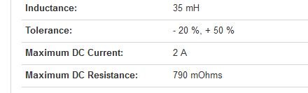
Instead of using these huge MOT for a HA, would the Hammond 159ZC be ok ?
It’s rated 60mH, 2A, dc resistance 0.7 ohm
Just not sure how to size the choke value for a 32 ohm headphone so the bass don’t roll off to early.
Hoping for a positive answer so I can build this HA very soon.
Thanks
Eric
It’s rated 60mH, 2A, dc resistance 0.7 ohm
Just not sure how to size the choke value for a 32 ohm headphone so the bass don’t roll off to early.
Hoping for a positive answer so I can build this HA very soon.
Thanks
Eric
Yes that Hammond is going to work just fine. Bass falloff only happens if you deplete the magnetic stored energy from speakers running at 5w at 8ohms. 32ohm headphones running 50mW is not going to be a problem. Use larger output cap if you are worried about bass rolloff.
-3dB point for 32ohm and 2200uF is 2.2Hz. It will be flat to 9Hz. If you use 4700uF you will have more than you need.
-3dB point for 32ohm and 2200uF is 2.2Hz. It will be flat to 9Hz. If you use 4700uF you will have more than you need.
Thanks a lot !
Is there anything to fine tune with the circuit value since my choke is not 100mH ?
Eric
Is there anything to fine tune with the circuit value since my choke is not 100mH ?
Eric
The mH value is not important as long as > 50mH for headphones and DCR is within range. For 1.3A you want overall 1.5ohms (Inductor plus resistor). For 2.5ohm overall it is around 800mA. Strictly for headphone use something like 4.7ohms will work fine and keep the heat output much lower.
X, You mention the Erse 20 mh SQ chokes. What would be the rolloff for those into 25 ohm loads? The can take a lot of current. I asked an engineer there once and he said they will not saturate at 6 amps.
Thanks,
Skkip
Thanks,
Skkip
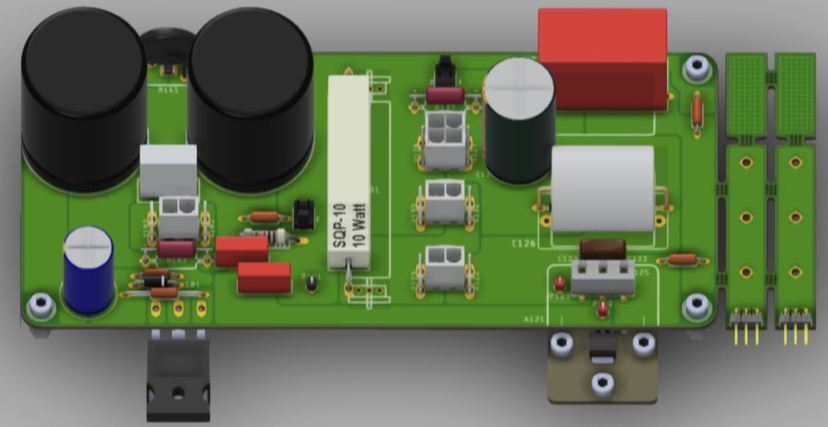
Superb PCB layout that JPS64 is making for the LuFo Lite.
Thanks for sharing X.
Could the potentially hot resistors be located away from the Cap Mx electrolytics?
How about some pads to allow a TO247 package power resistor, mounted on the heatsink?
Yes, I have already requested that extra space be given for the resistors to be farther away from the caps. There is also option for a single main board mounted resistor in case one is running lower bias current for strictly headphone amp application. Circa 200mA is all that is needed for 32 ohm headphones as a HPA. A provision for connectors to mount an external flying leads heatsinked resistor is provided - either Faston tabs or Molex MiniFit Jr connectors. Layout is already done so can’t add TO-247 resistors. Here is render showing case with single on board resistor for headphone amp application.
Attachments

Last edited:
I wonder if a 20mH iron core speaker inductor would be enough for a 32ohm headphone amp?
ERSE Super Q 20mH 16 AWG 500W Inductor Crossover Coil
ERSE Super Q 20mH 16 AWG 500W Inductor Crossover Coil
My question exactly. I have two on the shelf and have your Lu1014 boards and a stash of calibrated LUs.
I forgot that I ran the sims a while back. Yes, 20mH is enough to double the output swing into 32ohms.
Logically you should double the mH if you double the speaker impedance....
So these 20 mH 6A crossover inductors could be candidate for 4ohm speaker LuFo with high bias let's say 4A
So these 20 mH 6A crossover inductors could be candidate for 4ohm speaker LuFo with high bias let's say 4A
Lower impedance speaker requires more current, and that would require more stored magnetic energy, no?
For filters, inductor values scale with impedance, but this is not a filter but rather, a dynamic storage “battery”.
That Jantzen is an iron core crossover inductor with ferrite discs. I don’t know how much DC current that can take without saturating. It’s cheap enough to try?
For filters, inductor values scale with impedance, but this is not a filter but rather, a dynamic storage “battery”.
That Jantzen is an iron core crossover inductor with ferrite discs. I don’t know how much DC current that can take without saturating. It’s cheap enough to try?
Last edited:
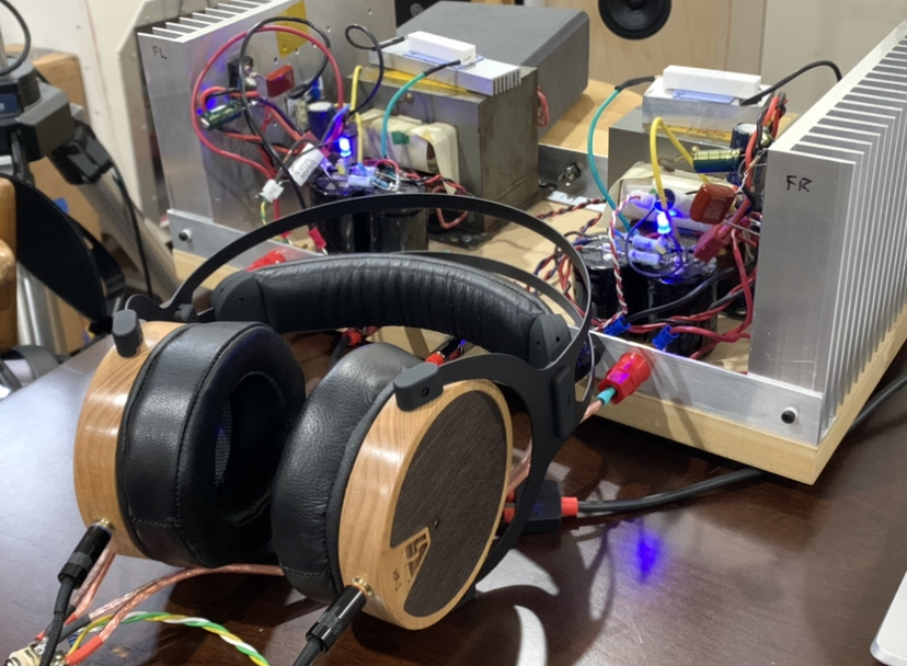
I just got a pair of LSA HP-2 dynamic headphones - these are waveguide loaded (front horn), closed back, graphene coated diaphragm drivers, 105dB/mW and 33ohms. Connected them to the LuFo Lite. In a word - wow! These are excellent headphones and the resolution and texture of the bass can really be heard nicely, the midrange is butter smooth and natural sounding. Very comfy and lightweight with real leather ear pads, headband, and wooden ear cups.
Attachments

Have you ordered your first test PCBs? If so would 4-6 weeks be a likely timeframe for ones we might purchase? (optimistic, of course). Thanks
No not yet, plan to soon. They should be here within 10 days if I order tonight. Sort of trying to consolidate a few more boards in same shipment. We will need to build a verification build. It’s pretty simple so I don’t expect any problems.
Here are the LuFo Lite BOM, schematics, and stuffing diagram.
Attachments
Last edited:
Thanks X.
Here's another possible inductor for LuFo Lite, very cost effective!
https://www.mouser.co.uk/ProductDet...=/ha2pyFaduiGNLTBDVglz4UIrU7r3F4dDGW6C96rclk=
Here's another possible inductor for LuFo Lite, very cost effective!
https://www.mouser.co.uk/ProductDet...=/ha2pyFaduiGNLTBDVglz4UIrU7r3F4dDGW6C96rclk=
Attachments
- Home
- Amplifiers
- Headphone Systems
- LuFo Lite - a 1 Transistor SE Class A Headphone Amp